Variable crown roller for devices for processing continuous web material and device comprising said roller

a technology of continuous web material and crown roller, which is applied in the direction of manufacturing tools, portable power-driven tools, lighting and heating apparatus, etc., can solve the problems of obviating this drawback, reducing the so as to achieve the effect of modifying the amount of bending of the roller

Inactive Publication Date: 2007-01-18
FABIO PERINI SPA
View PDF26 Cites 6 Cited by
  • Summary
  • Abstract
  • Description
  • Claims
  • Application Information

AI Technical Summary

Benefits of technology

[0011] The object of the present invention is to produce a pressure roller, particularly although not exclusively for an embossing unit designed to process a web material in cooperation with an embossing cylinder, which overcomes the drawbacks of traditional rollers and allows optimum working conditions to be obtained, compensating the bending deformations of the pressure roller and of the cylinder cooperating therewith, even when the working conditions vary and the amount of bending of the rollers is thus modified.

Problems solved by technology

Notwithstanding the architecture of the embossing device, drawbacks that will be explained hereunder occur, caused by the bending deformation of the cylinders, induced by the high operating pressures.
This bending deformation, with consequent formation of a camber on the axis both of the pressure roller and of the embossing cylinder, causes a defect in embossing, which is more marked along the edges and less marked in the central area of the web material.
However, this solution has the serious drawback of producing transverse forces on the web material and leads to rapid wear of the mechanical parts.
Alternative solutions attempting to obviate this drawback have proved to be somewhat impractical and determine problems of another type.
These systems have considerable drawbacks both due to their complexity and due to the high dynamic stresses to which the members forming the roller, particularly the supporting bearings and the cylindrical mantle, are subjected.
This solution is considerably limited due to the fact that the crown is fixed and therefore suitable to compensate bending deformation only in one working condition, that is, only with one value of reciprocal stress between the rollers.
When the pressure requires to be varied, for example to obtain different effects or processing conditions of the material in the nip between the rollers, the crown imposed on the surface of the pressure roller is either excessive with respect to the bending deformation, causing a defect opposed to that of said deformation, or insufficient and thus unable to compensate bending deformation.

Method used


Image

  • Variable crown roller for devices for processing continuous web material and device comprising said roller
  • Variable crown roller for devices for processing continuous web material and device comprising said roller
  • Variable crown roller for devices for processing continuous web material and device comprising said roller

Examples


Embodiment Construction

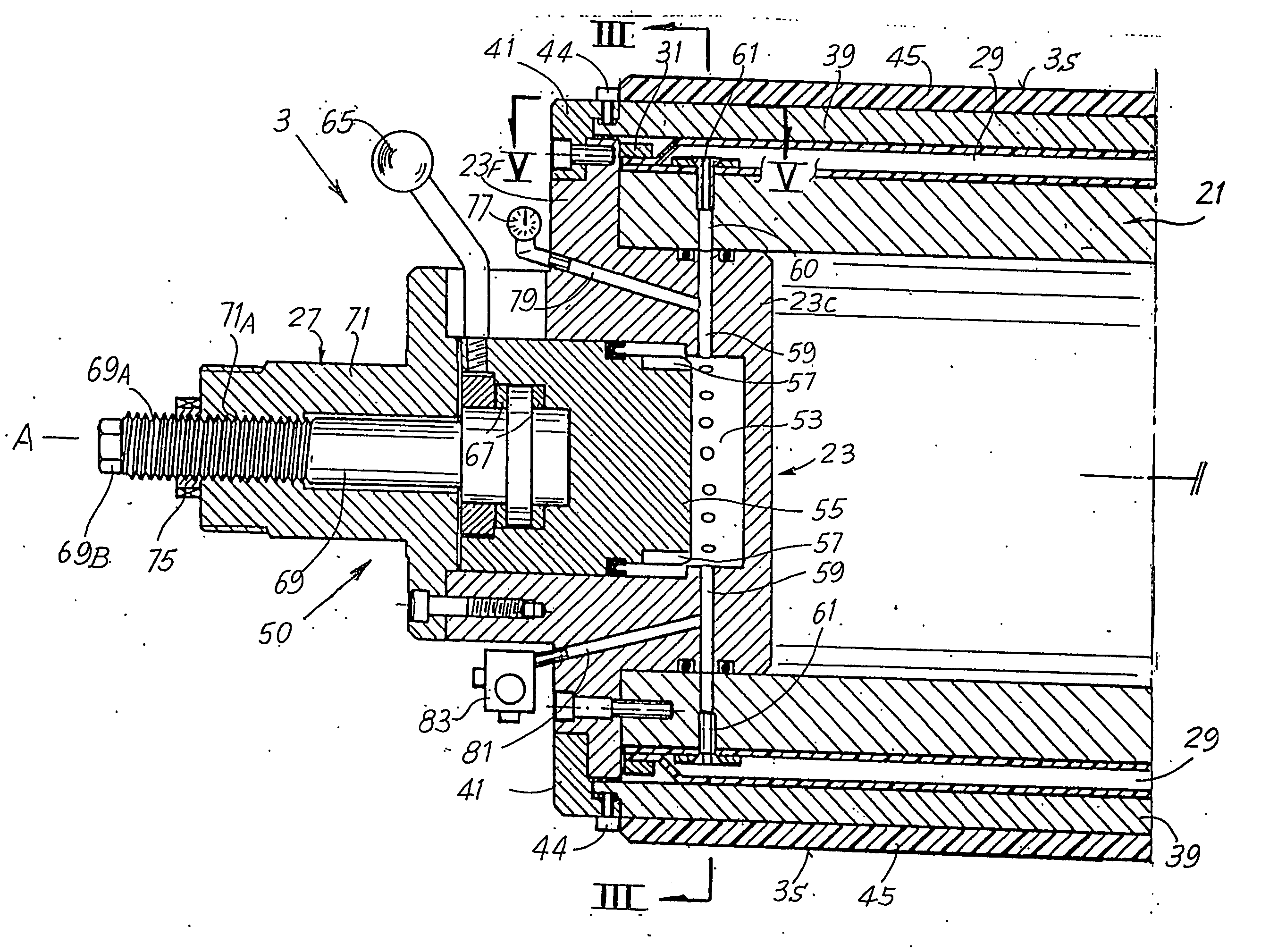
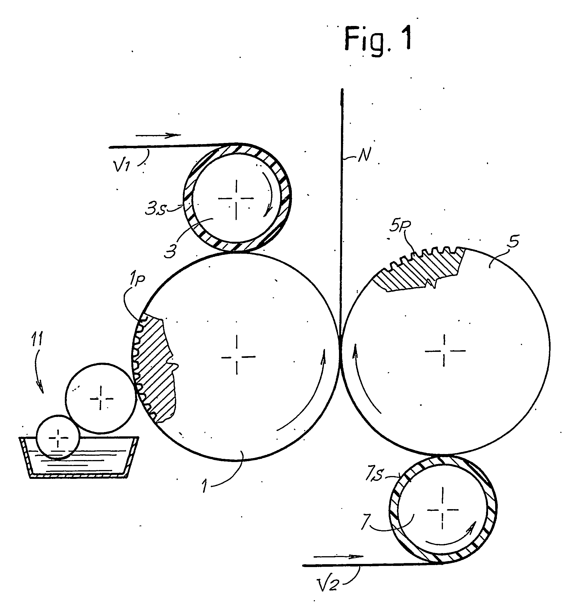
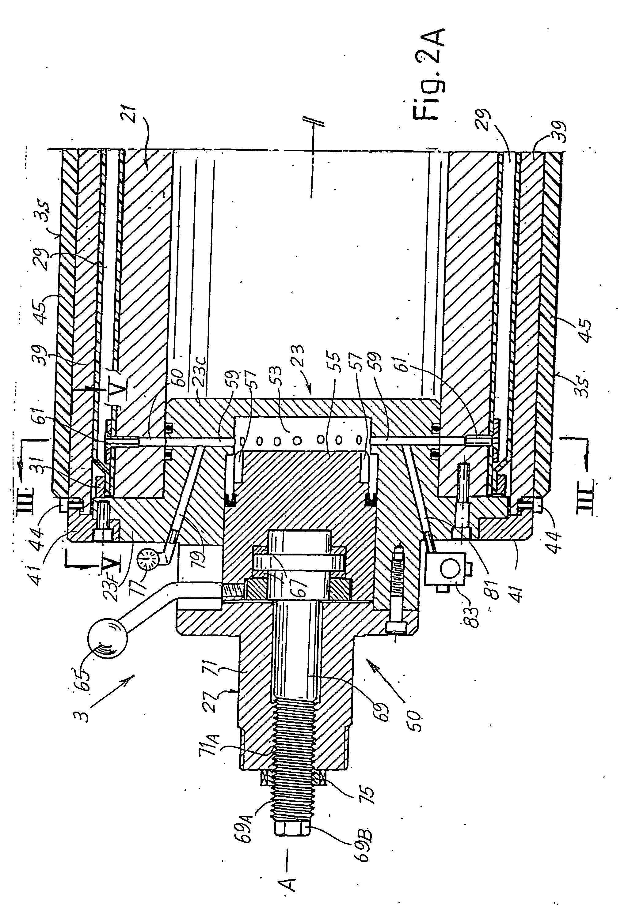
[0026]FIG. 1 very schematically shows an embossing unit to which the invention may be applied. The unit comprises a first embossing cylinder 1, equipped with protuberances or projections 1P, cooperating with a first pressure roller 3. The pressure roller 3 is provided with a coating in a yielding material, such as rubber, that defines the outer lateral surface 3S. The roller 3 is produced as shown in FIGS. 2A, 2B and 3 and as described hereunder. Disposed parallel to the embossing cylinder 1 is a second embossing cylinder 5, equipped with protuberances 5P and cooperating with a pressure roller 7, also coated in yielding material defining an outer lateral surface 7S, and produced in the manner shown and described hereunder. A glue dispenser 11, which applies glue to the protuberances produced through embossing between the roller 3 and the cylinder 1 on a first ply V1 of paper or another embossable material, cooperates with the embossing cylinder 1. This ply is joined by lamination an...


PUM

PropertyMeasurementUnit
thrustaaaaaaaaaa
movementsaaaaaaaaaa
pressureaaaaaaaaaa

Abstract

A pressure roller (3; 7) for devices for processing continuous web materials is described, comprising a lateral surface (3S; 7S), including a regulating system (29, 50) to impose an adjustable crown of the lateral surface (3S; 7S) of the roller deforming said lateral surface.

Description

TECHNICAL FIELD [0001] The present invention relates to a roller for devices for processing continuous web materials, and more specifically a pressure roller cooperating with a second roller or cylinder, with which it forms a nip through which the web material to be processed is fed, to be subjected to the action of the roller and of the cylinder pressed against each other. [0002] The invention also relates to a device for processing or treating web material comprising a pressure roller and a cylinder or counter-roller cooperating therewith to form a nip through which the web material to be processed is fed. STATE OF THE ART [0003] In many industrial applications it is necessary to process an essentially continuous web material, such as a plastic film, a paper web material, a non-woven fabric, a metallic sheet, or the like. These web materials are fed through a nip between two rollers or cylinders pressed against each other even at high pressures. [0004] Operations of this type that...

Claims


Application Information

Patent Timeline
Patent Type & Authority Applications(United States)
IPC IPC(8): F28F5/02B31F1/07F16C13/00
CPCB31F1/07F16C13/026B31F2201/073B31F2201/0723
Inventor BIAGIOTTI, GUGLIEMOBENVENUTI, ANGELO
Owner FABIO PERINI SPA
Why Eureka
Try Eureka