Control system for vehicles

a technology for controlling systems and vehicles, applied in the direction of vehicle position/course/altitude control, process and machine control, instruments, etc., can solve the problem of difficult control of the controlled vehicle, and achieve the effect of eliminating errors

Active Publication Date: 2007-01-25
TEXTRON INNOVATIONS
View PDF6 Cites 31 Cited by
  • Summary
  • Abstract
  • Description
  • Claims
  • Application Information

AI Technical Summary

Benefits of technology

[0007] This object is achieved by providing a system allowing easy control of the position and velocity of a controlled vehicle relative to a reference vehicle or object. A sensor system disposed on the controlled vehicle senses the position of the controlled vehicle and inertial movement of the controlled vehicle, and a receiver disposed on the controlled vehicle receives transmitted data communicating the position and movement of a reference vehicle. The sensor system communicates data representing the position and the inertial movement of the controlled vehicle to a control system disposed on the controlled vehicle for comparison to the data from the receiver, allowing calculation of the position and motion of the controlled vehicle relative to the reference vehicle. Data representing a selected position and / or velocity of the controlled vehicle relative to the reference vehicle is compared to the calculated relative position and relative velocity, and the control system commands devices on the controlled vehicle to maneuver the controlled vehicle so as to eliminate the error between the calculated and selected values.

Problems solved by technology

If an operator wants to operate a controlled vehicle relative to a moving object, such as another vehicle, the operator must consider the position and velocity of both the controlled vehicle and the object, making controlling the controlled vehicle a more difficult task.

Method used


Image

  • Control system for vehicles
  • Control system for vehicles
  • Control system for vehicles

Examples


Embodiment Construction

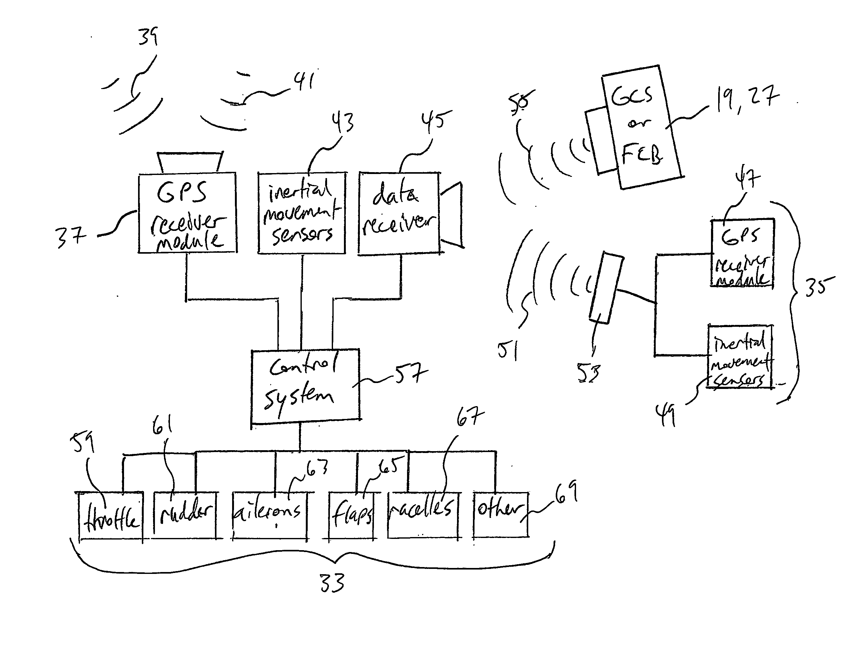
[0020] The present invention provides a system for controlling a controlled vehicle in relation to a reference vehicle using relative velocities, which are determined by comparing the position and movement of the controlled vehicle with the position and movement of a known point.

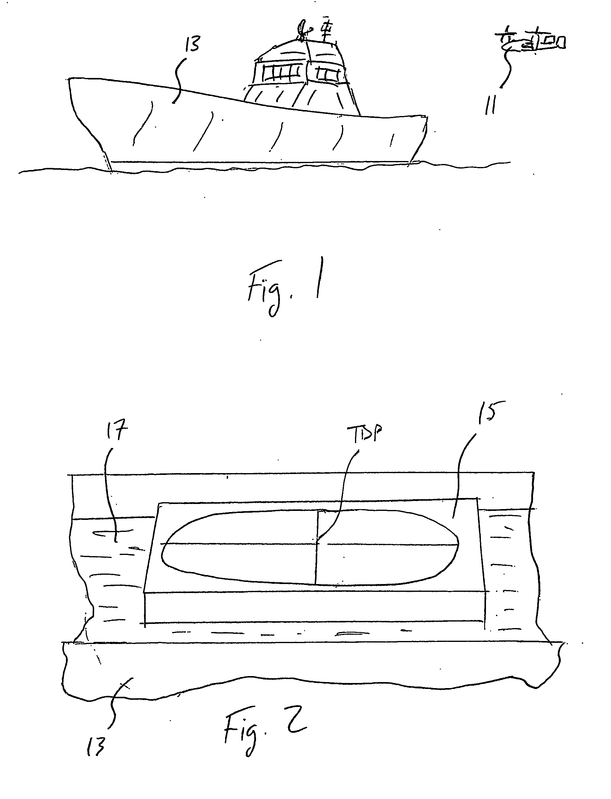
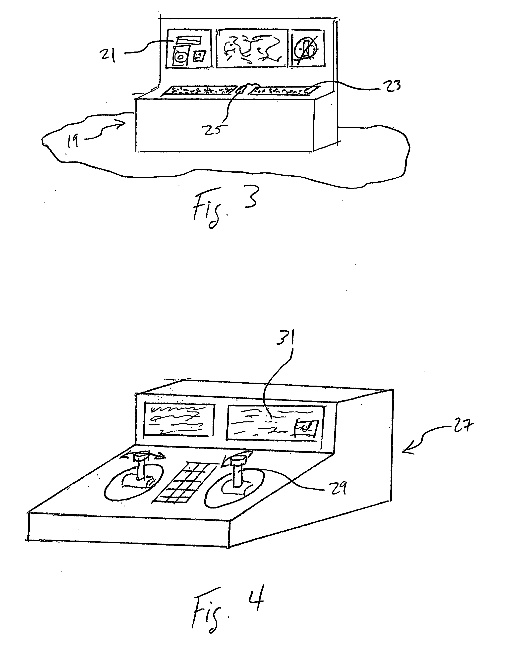
[0021] For purposes of illustrating the system of the invention, the system will be described in reference to its use as a control system for an aircraft operating in conjunction with a ship at sea. The known point on the ship may be a touchdown point (TDP) for landing the aircraft. The relative velocity is zero if the aircraft is moving at the same velocity, i.e., same speed and direction, as the TDP. This invention allows precise aircraft velocity control relative to the TDP regardless of the speed of the TDP or the velocity and direction of the relative wind. A unique characteristic of this system is that the control of the aircraft velocity is independent of the aircraft heading, as the system allows an...


PUM


Abstract

A system for controlling flight of an aircraft has sensors (37, 43), a receiver (45), and a digital control system (57), all of which are carried aboard the aircraft. The sensors (37, 43) determine the position of the aircraft relative to the earth and the inertial movement of the aircraft. The receiver (45) receives transmitted data (51, 55) communicating the position and movement of a reference vehicle relative to the earth. The control system (57) calculates the position and velocity of the aircraft relative to the reference vehicle using the data from the sensors (37, 43) and the receiver (45) and then commands flight control devices (33) on the aircraft for maneuvering the aircraft in a manner that maintains a selected position and / or velocity relative to the reference vehicle. The system allows use of a graphical or tactile user interfaces.

Description

TECHNICAL FIELD [0001] The present invention relates in general to the field of control systems for vehicles. In particular, the present invention relates to a control system for causing a vehicle to have a selected position or selected velocity relative to a reference vehicle. DESCRIPTION OF THE PRIOR ART [0002] Remote control of an aircraft is typically done by commanding the airspeed or inertial speed (groundspeed) of the vehicle, and the direction of the velocity is selected by controlling the heading of the vehicle. The control inputs are usually commands given in terms of the longitudinal, lateral, or directional axis of the aircraft. Therefore, if an operator controlling the aircraft wants the aircraft to move in a certain direction, the operator must know in which direction the aircraft is pointing to determine which axis of control must be used, and in which direction, in order to make the aircraft move in the desired direction. When controlling the aircraft relative to ano...

Claims


Application Information

Patent Timeline
Patent Type & Authority Applications(United States)
IPC IPC(8): G06F17/00B64C13/20B64C39/02G05D1/02
CPCB64C13/20B64C39/024B64C2201/021B64C2201/086B64C2201/108B64C2201/187B64C2201/165G05D1/0027G05D1/0684B64C2201/205B64C2201/141B64U70/60B64U10/25B64U30/20B64U2201/10B64U80/84B64U50/13
Inventor BUILTA, KENNETH E.HARRIS, JAMES E.HONZA, BRYAN P.EPP, JEFFREY W.SCHULTE, KYNN J.
Owner TEXTRON INNOVATIONS
Why Eureka
Try Eureka