System, method and program for designing a utility facility and method for manufacturing a product by the utility facility

a utility facility and system technology, applied in the field of system, computer implemented method and computer program product design of utility facility, can solve the problems of unnecessarily large size of utility facility, and large excess capacity of utility facility once included in the factory

Inactive Publication Date: 2007-03-15
KK TOSHIBA
View PDF22 Cites 19 Cited by
  • Summary
  • Abstract
  • Description
  • Claims
  • Application Information

AI Technical Summary

Problems solved by technology

As a result, a utility facility with an unnecessarily large size is designed.
A utility facility once included in the factory is not capable of low capacity operation by reducing quantities of utilities to be supplied.
In a case where large utility specifications for usage are calculated, compared with utilities consumed during actual operations, the excessive capacity of the utility facility is large.
For example, a production line for wafers, each with a diameter of 300 mm, indicates extremely large utility specifications, and the excessive capacity of a utility would be larger than ever.
In this case, running costs become increased, and there also exists a problem from the viewpoint of energy savings when actual...

Method used


Image

  • System, method and program for designing a utility facility and method for manufacturing a product by the utility facility
  • System, method and program for designing a utility facility and method for manufacturing a product by the utility facility
  • System, method and program for designing a utility facility and method for manufacturing a product by the utility facility

Examples


first embodiment

(First Embodiment)

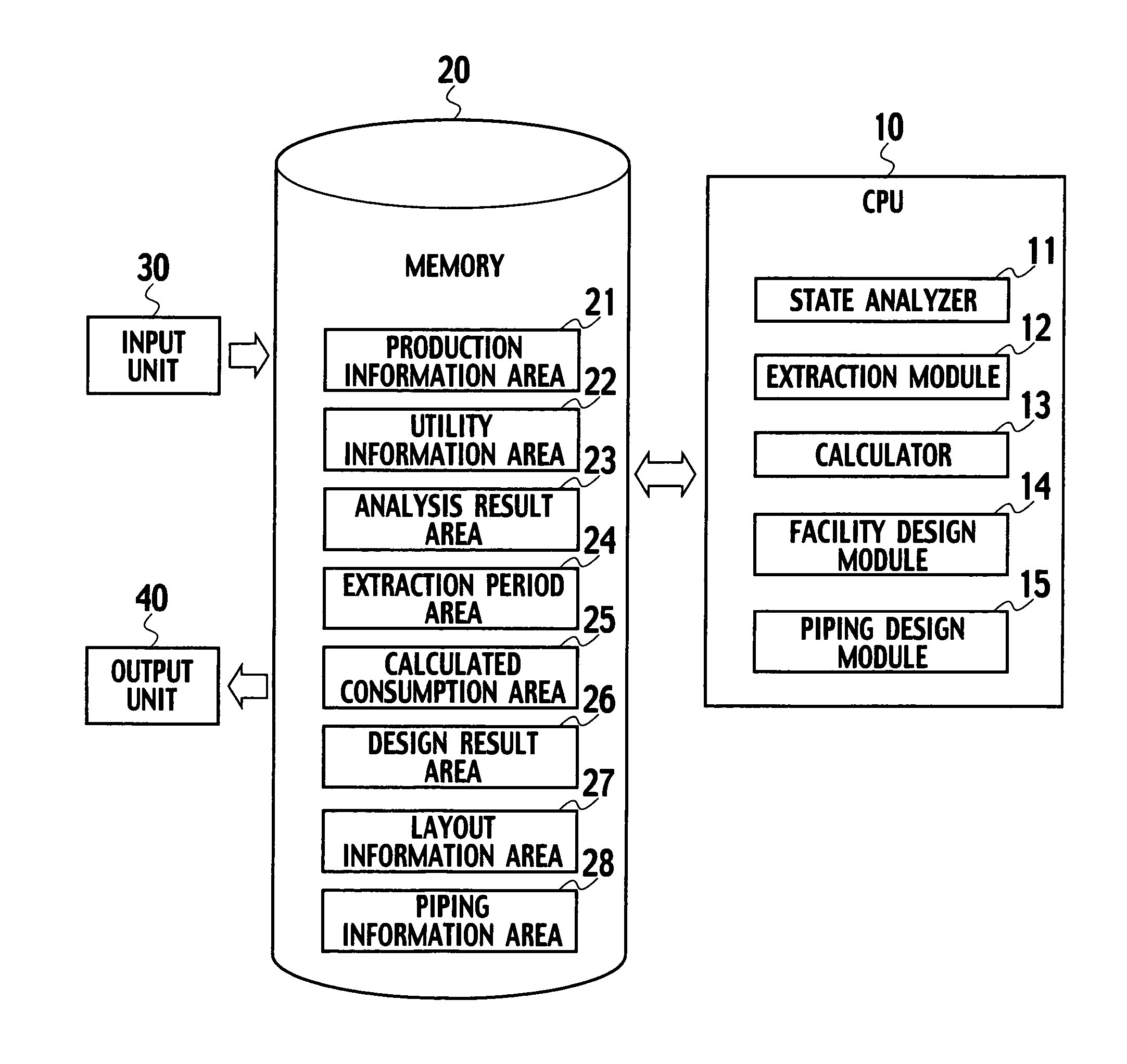
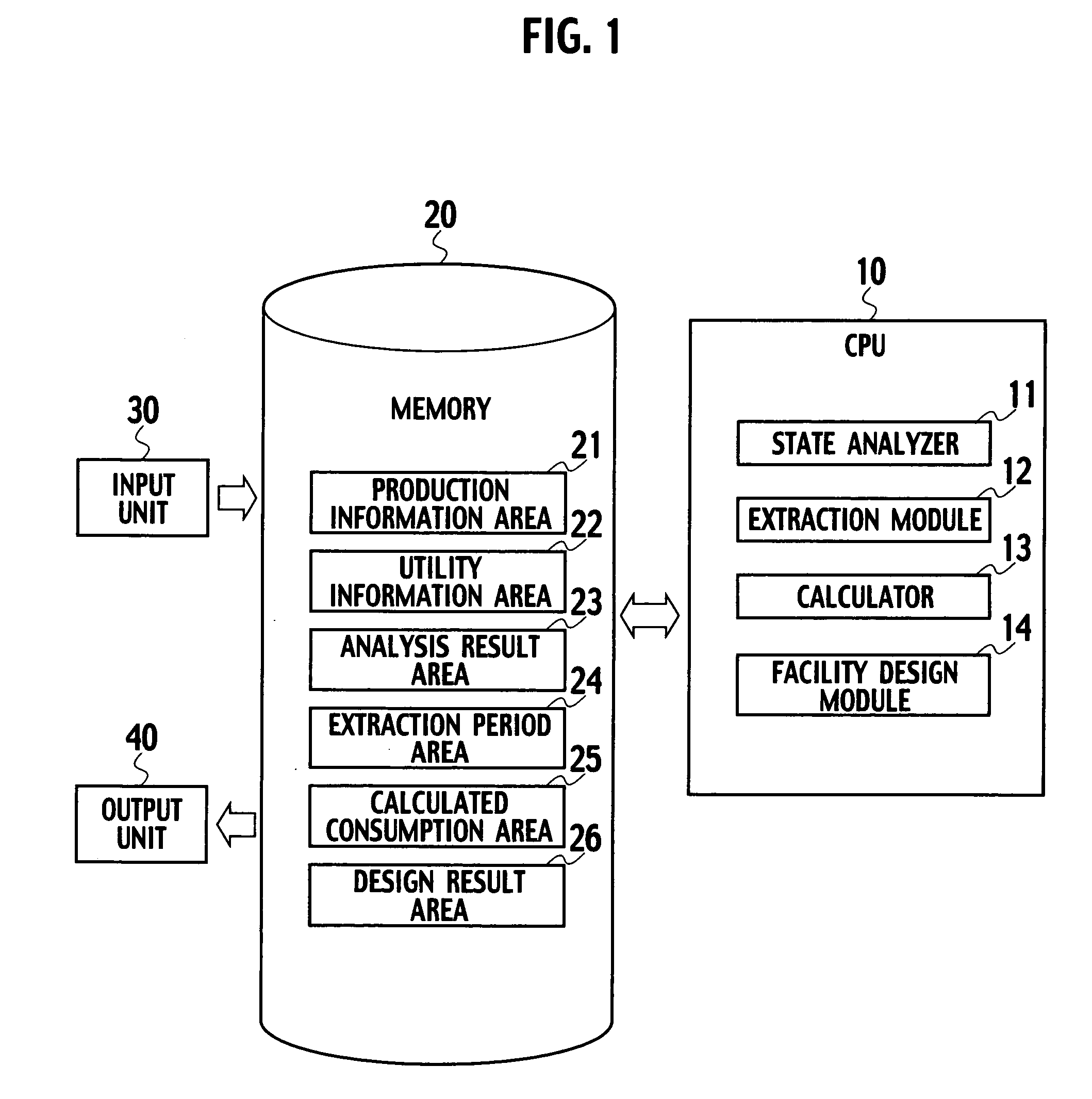
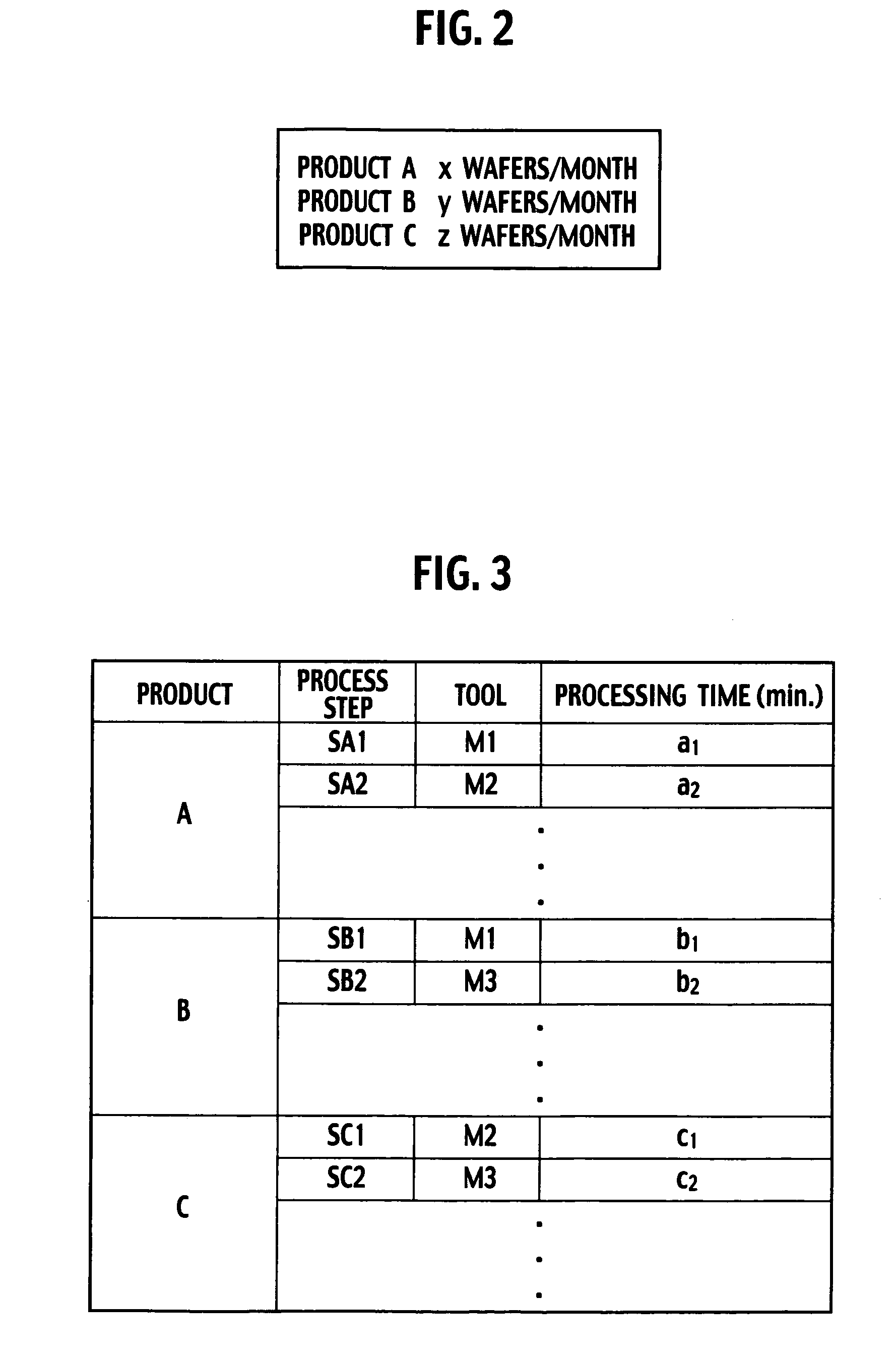
[0037] A system for designing a utility facility according to a first embodiment of the present invention includes a state analyzer 11, an extraction module 12, a calculator 13 and a facility design module 14, as shown in FIG. 1. The state analyzer 11 analyzes operational states of a plurality of tools included in a production line for producing products, respectively. Each of the operational states is assumed based on production information of the products. The extraction module 12 extracts an operational period and a standby period of each of the tools on the basis of the result of the state analysis of the tools. Based on the operational periods and the standby periods, the calculator 13 calculates changes in a quantity of utilities consumed by each of the tools with respect to time, based on quantities of utilities consumed by each of the tools in operation and in standby. Based on changes in the quantity of utilities consumed by all of the tools with respect t...

second embodiment

(Second Embodiment)

[0079] A system for designing a utility facility according to a second embodiment of the present invention is different from the system for designing a utility facility shown in FIG. 1 in the point that, as shown in FIG. 19, the system according to the second embodiment further includes a piping design module 15, a layout information area 27 and a piping information area 28. The other configuration of the system for designing a utility facility according to the second embodiment is the same as the configuration of the system according to the first embodiment.

[0080] Layout information of the production line, to which the utility facility supplies utilities, is stored in the layout information area 27. The “layout information of the production line” is information for indicating where in a factory each of the tools included in the production line are to be installed.

[0081] The piping design module 15 designs piping through which the utility facility supplies utili...


PUM


Abstract

A system for designing a utility facility includes a state analyzer analyzing operational states of tools included in a production line, an extraction module extracting an operational period and a standby period of each of the tools, a calculator calculating changes in a quantity of utilities consumed by the tools in operation and in standby, based on the operational periods and the standby periods, and a facility design module designing at least any of a utility facility for supplying utilities to the tools and a utility facility for disposing of utilities discharged from the tools.

Description

CROSS REFERENCE TO RELATED APPLICATIONS AND INCORPORATION BY REFERENCE [0001] This application is based upon and claims the benefit of priority from prior Japanese Patent Application P2005-263519 filed on Sep. 12, 2005; the entire contents of which are incorporated by reference herein. BACKGROUND OF THE INVENTION [0002] 1. Field of the Invention [0003] The present invention relates to facility design technology, particularly for a system, a computer implemented method and a computer program product for designing a utility facility, based on utility consumption of a production line. [0004] 2. Description of the Related Art [0005] In the case of the related art, quantities of utilities, such as electricity and gases, which are used by tools for the production of products, are calculated by multiplying utility specification for usage of each tool, by corresponding coefficients (load factors), respectively. As is often the case, the utility specifications of each of the tools demand uti...

Claims


Application Information

Patent Timeline
IPC IPC(8): G05B19/418
CPCG05B19/41865G06Q10/06G05B2219/32365G05B2219/31455Y02P90/02
Inventor MASUDA, TOSHIKATSUSHINKI, TOSHINORISAMATA, SHUICHIMIKATA, YUUICHI
Owner KK TOSHIBA
Why Eureka
Try Eureka