Method and Apparatus for Virtual Reality Presentation of Civil Engineering, Land Planning and Infrastructure

Inactive Publication Date: 2007-04-05
RDV SYST
View PDF6 Cites 31 Cited by
  • Summary
  • Abstract
  • Description
  • Claims
  • Application Information

AI Technical Summary

Benefits of technology

[0008] Accordingly, it is a principal object of the present invention to overcome the disadvantages of prior art systems for evaluating and interacting with large scale designs. This is provided for in the present invention by a method and apparatus for exporting and converting CAD and/or GIS data to a scene-graph abstraction of a vi

Problems solved by technology

Unfortunately, in large scale projects, and in particular those having GIS based data, these techniques are computationally intensive, and thus the photo-realistic results are viewable as a single raster image or stored as a seri

Method used


Image

  • Method and Apparatus for Virtual Reality Presentation of Civil Engineering, Land Planning and Infrastructure
  • Method and Apparatus for Virtual Reality Presentation of Civil Engineering, Land Planning and Infrastructure
  • Method and Apparatus for Virtual Reality Presentation of Civil Engineering, Land Planning and Infrastructure

Examples


Embodiment Construction

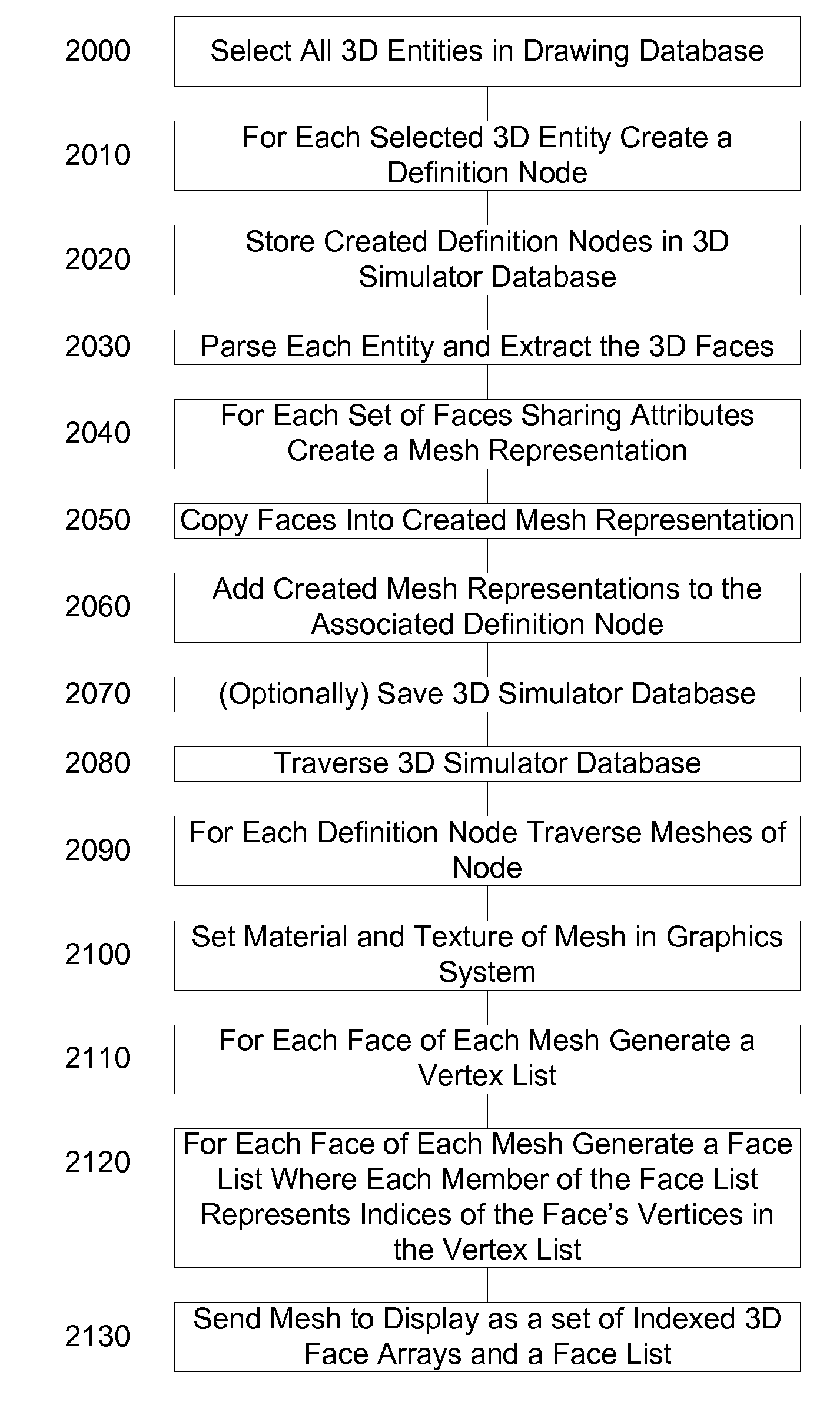
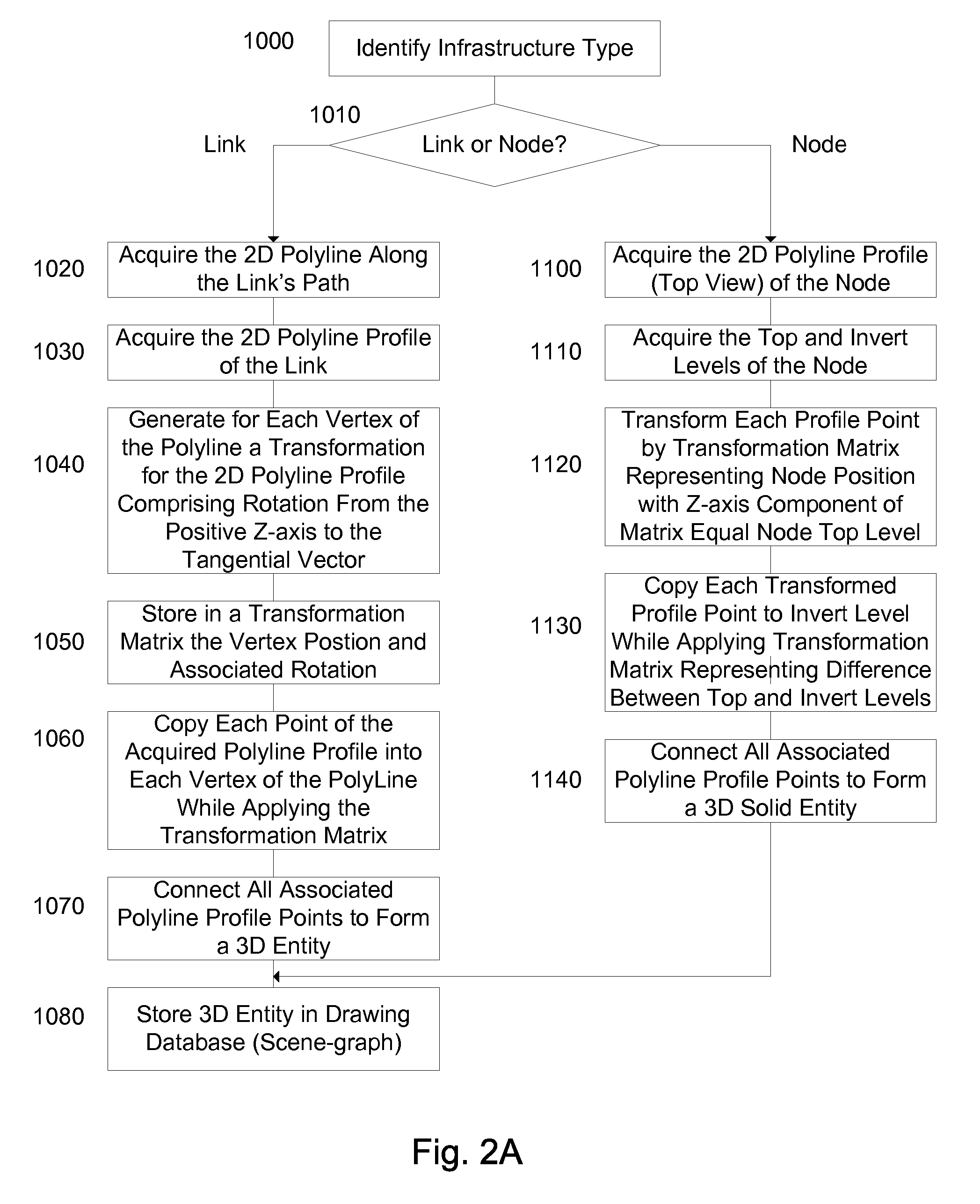
[0055] The present embodiments enable a method and apparatus for exporting and converting CAD and / or GIS data to a scene-graph abstraction of a virtual reality scene. 3D geometry information and assignments for lighting, coloring, texturing and shading is stored in the scene-graph preferably including an object hierarchy with uniquely identified objects and sub-objects in the scene-graph. In an exemplary embodiment animation control is provided for objects which move over time.

[0056] The invention further provides for a viewing application that takes the generated scene-graph and displays it on a monitor. In an exemplary embodiment the viewing application displays the scene-graph via a graphics card subsystem of a viewing computer. Preferably, all processing required for viewing of visual information occurs in the graphics pipeline of the viewing computer. Further preferably the graphics pipeline utilizes either OpenGL or DirectX protocols, with an optimizing decision regarding whi...


PUM


Abstract

A computer implemented method of visualizing an infrastructure comprising: acquiring a cross section definition, the definition comprising points defining a link and link information, each of the points exhibiting a type; creating at least one three dimensional face linking points of a same type; assigning a face rendering for each of the created at least one three dimensional faces with a material definitional associated with the link information; and displaying the faces with the rendering. The invention also provides for a computing system operable to: acquire a cross section definition, the definition comprising points defining a link and link information, each of the points exhibiting a type; create at least one three dimensional face linking points of a same type; and assign a face rendering for each of the created at least one three dimensional faces with a material definitional associated with the link information.

Description

CROSS-REFERENCE TO RELATED APPLICATION [0001] This application claims priority from U.S. Provisional Patent Application Ser. No. 60 / 723,011 filed Oct. 4, 2005 entitled “A Virtual Reality Based System for the 3D Planning, Visualization and Analysis of Large Scale Engineering Projects in the Areas of Civil Engineering, Land Planning and Infrastructure Development” the entire contents of which are incorporated herein by reference.BACKGROUND OF THE INVENTION [0002] The invention relates generally to the field of computer aided design and geographic information systems, and in particular to a method of converting a computer aided design of a large scale project to a virtual reality based model. [0003] Computer aided design (CAD) applications are used for both small and large scale products. For small scale projects, typically all the surfaces, shapes and interactions are defined by the user, and the application may generate a detailed 3 dimensional (3D) model which is viewable from any a...

Claims


Application Information

Patent Timeline
IPC IPC(8): G06F17/10
CPCG06F17/5004G06F30/13
Inventor ELSBERG, NATHANHAZANOV, ALEX
Owner RDV SYST
Why Eureka
Try Eureka