Rotating Electrical Machine and Method for Producing Such a Machine

a technology of rotating electrical machines and winding bars, which is applied in the direction of windings, synchronous machines, dynamo-electric components, etc., can solve the problems of additional complexity in the production of winding bars, and achieve the effect of reducing complexity and high dielectric strength

Active Publication Date: 2007-07-26
GENERAL ELECTRIC TECH GMBH
View PDF15 Cites 13 Cited by
  • Summary
  • Abstract
  • Description
  • Claims
  • Application Information

AI Technical Summary

Benefits of technology

[0009]One of numerous aspects of the present invention involves providing a rotating electrical machine in which a high dielectric strength, given r

Problems solved by technology

However, this precaution has the following disadvantages: while all the winding bars of the upper and lower layers have the same “pitch” or twisting angle in the end winding without any tangenti

Method used


Image

  • Rotating Electrical Machine and Method for Producing Such a Machine
  • Rotating Electrical Machine and Method for Producing Such a Machine
  • Rotating Electrical Machine and Method for Producing Such a Machine

Examples


Embodiment Construction

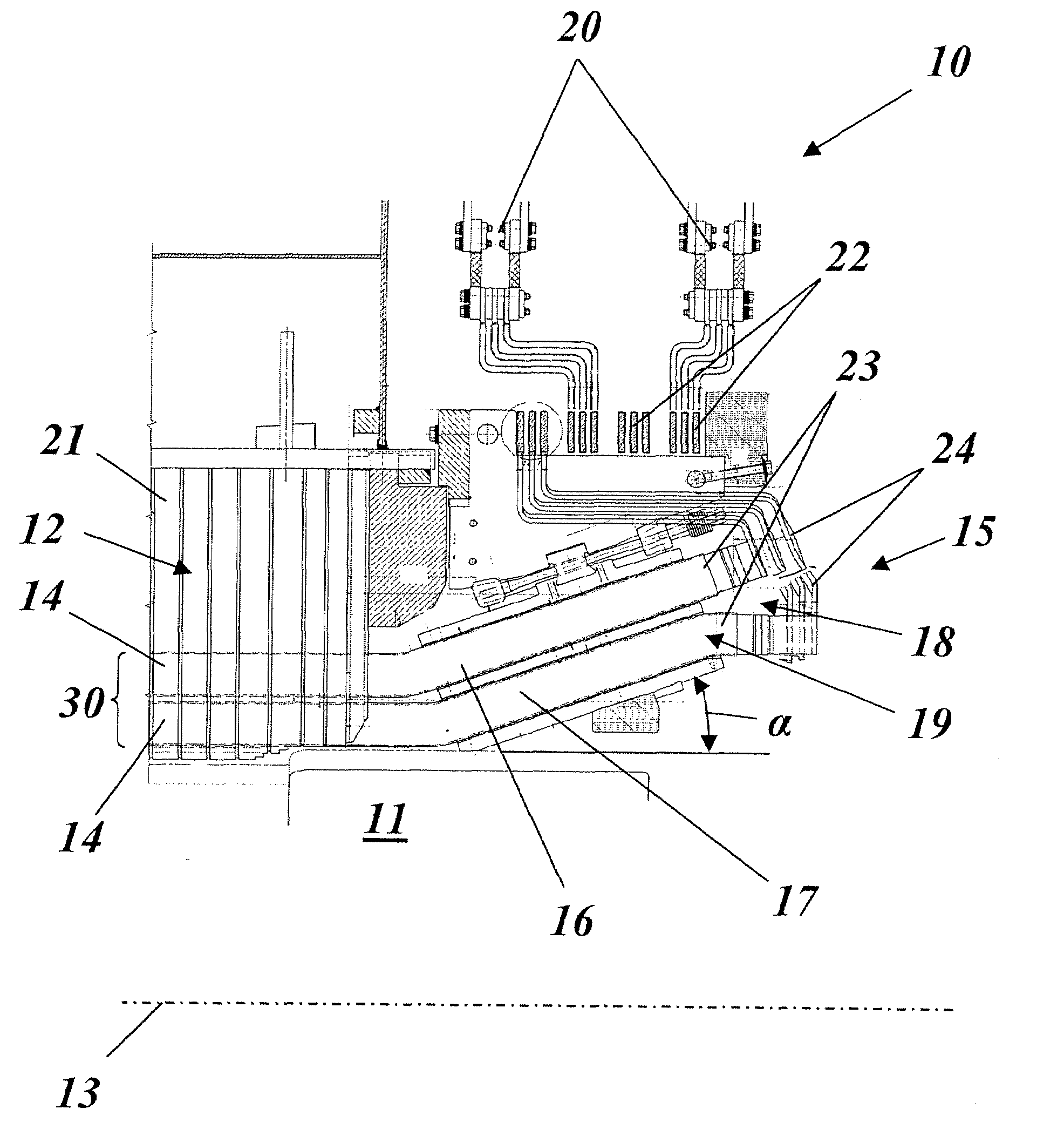
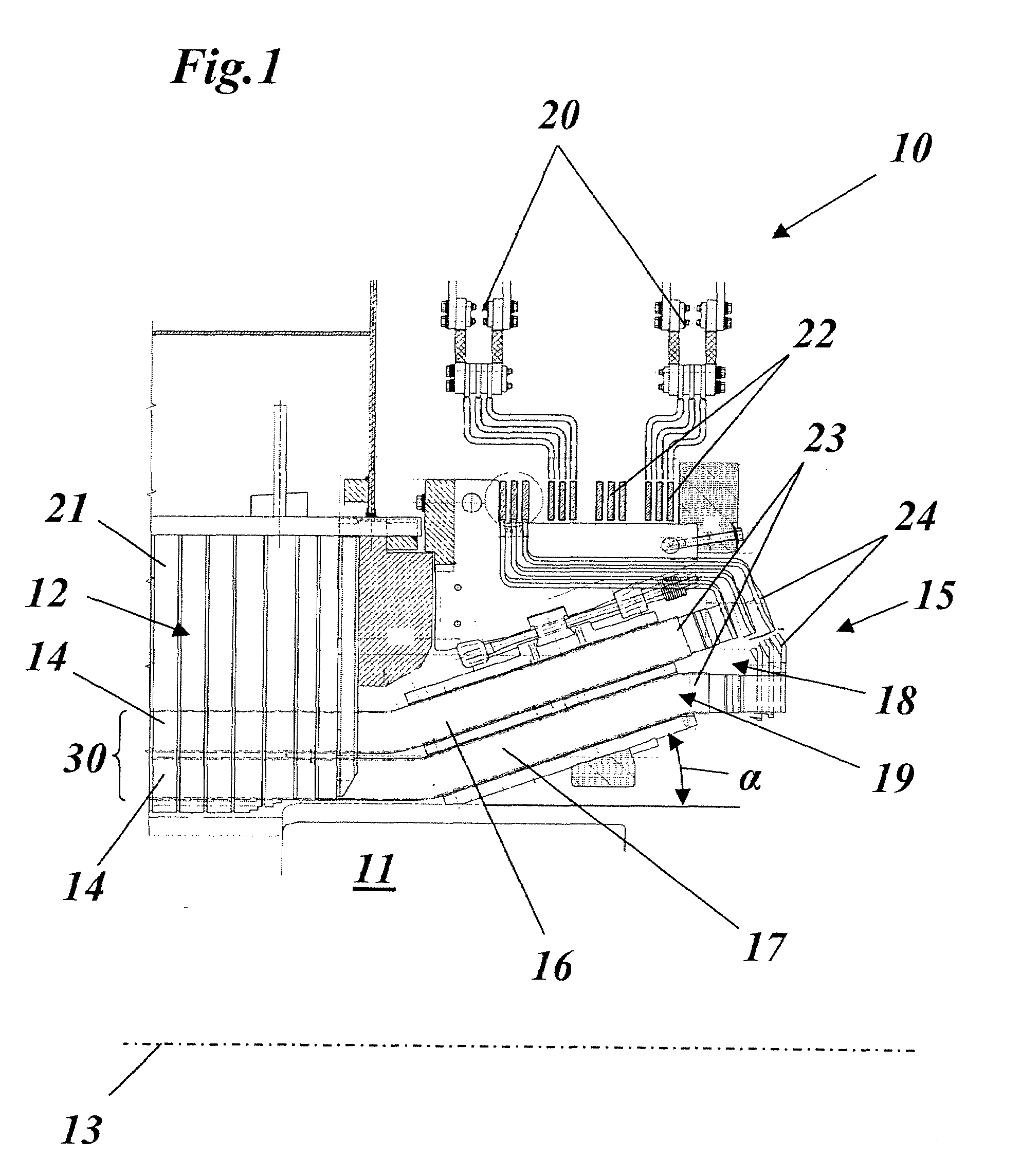
[0025]FIG. 1 illustrates, in longitudinal section, the connection-side end winding 15 of a rotating electrical machine 10 in accordance with one exemplary embodiment of the invention. The machine 10 has a rotor 11 (only indicated by the contour), which rotates about an axis 13 and is surrounded concentrically by a stator 12. The stator 12 comprises a stator body 21 in the form of a laminate stack, into which slots are introduced on the inner circumference for the purpose of accommodating the stator winding 30 formed from winding bars 14. Two winding bars 14 are arranged one above the other in each slot, these winding bars belonging to a lower layer 16 and an upper layer 17 of the stator winding 30.

[0026]The winding bars 14 of both layers 16, 17 emerge from the stator body 21 with their end sections and are bent outwards within the end winding 15 such that the end sections lie on a cone about the axis 13 with a cone angle α. At the same time, twisting of the end sections about a cons...


PUM


Abstract

A rotating electrical machine (10) has a rotor (11), which rotates about an axis (13) and is surrounded concentrically by a stator (12) having a stator winding (30) inserted into a stator body (21), the stator winding (30) including, in a concentric arrangement, a lower layer (16), which is more remote from the axis, and an upper layer (17), which is closer to the axis, of axially extending winding bars (14), which emerge from the stator body (21) at the ends of the stator (12) and are arranged, within an end winding (15), with their bar ends (23), on two concentric circles in pairs one above the other in the radial direction. With such a machine, simplified production of the stator winding (30) with, at the same time, a high dielectric strength is achieved by virtue of the fact that in those winding bars (14) of a pair which belong to different phases within a phase segregation, radial spreading (18) of the bar ends (23) is provided so as to increase the radial distance between the different phases.

Description

[0001]This application claims priority under 35 U.S.C. § 119 to Swiss patent application number 00107 / 06, filed 24 Jan. 2006, the entirety of which is incorporated by reference herein.BACKGROUND OF THE INVENTION[0002]1. Field of the Invention[0003]The present invention relates to the field of electrical machines. It relates to a rotating electrical machine and to a method for producing such a machine.[0004]2. Brief Description of the Related Art[0005]Such machines are known, for example, from DE-A1-197 26 563 or DE-A1-102 15 937.[0006]In large rotating electrical machines, such as turbogenerators, for example, in a power range of up to several 100 MW, the stator winding is constructed by winding bars having a rectangular cross section, which are inserted and wedged into axial slots provided for this purpose in the laminate stack. Two winding bars are often arranged one above the other in a lower layer and in an upper layer within the slots (see, for example, the aforementioned DE-A1...

Claims


Application Information

Patent Timeline
IPC IPC(8): H02K1/00H02K11/00H02K23/26H02K3/46
CPCH02K3/12H02K3/505H02K3/38
Inventor BAENZIGER, MATTHIASLADSTAETTER, WERNERSTALLONE, FRANCESCO
Owner GENERAL ELECTRIC TECH GMBH
Why Eureka
Try Eureka