Electric pump

a technology of electric pumps and impellers, applied in the direction of pump components, piston pumps, non-positive displacement fluid engines, etc., can solve the problems of impeller wear and fluctuation of fluid pressure, and achieve the effect of controlling the occurrence of unpleasant noise and reducing the vibration of the impeller

Inactive Publication Date: 2007-08-02
AISAN IND CO LTD
View PDF3 Cites 26 Cited by
  • Summary
  • Abstract
  • Description
  • Claims
  • Application Information

AI Technical Summary

Benefits of technology

[0007]It is an object of the present teachings to provide an electric pump capable of reducing th

Problems solved by technology

However, if air or foreign matter is mixed into the fluid drawn into the pump chamber, the fluid pressure acting on the impeller flu

Method used


Image

  • Electric pump
  • Electric pump
  • Electric pump

Examples


first embodiment

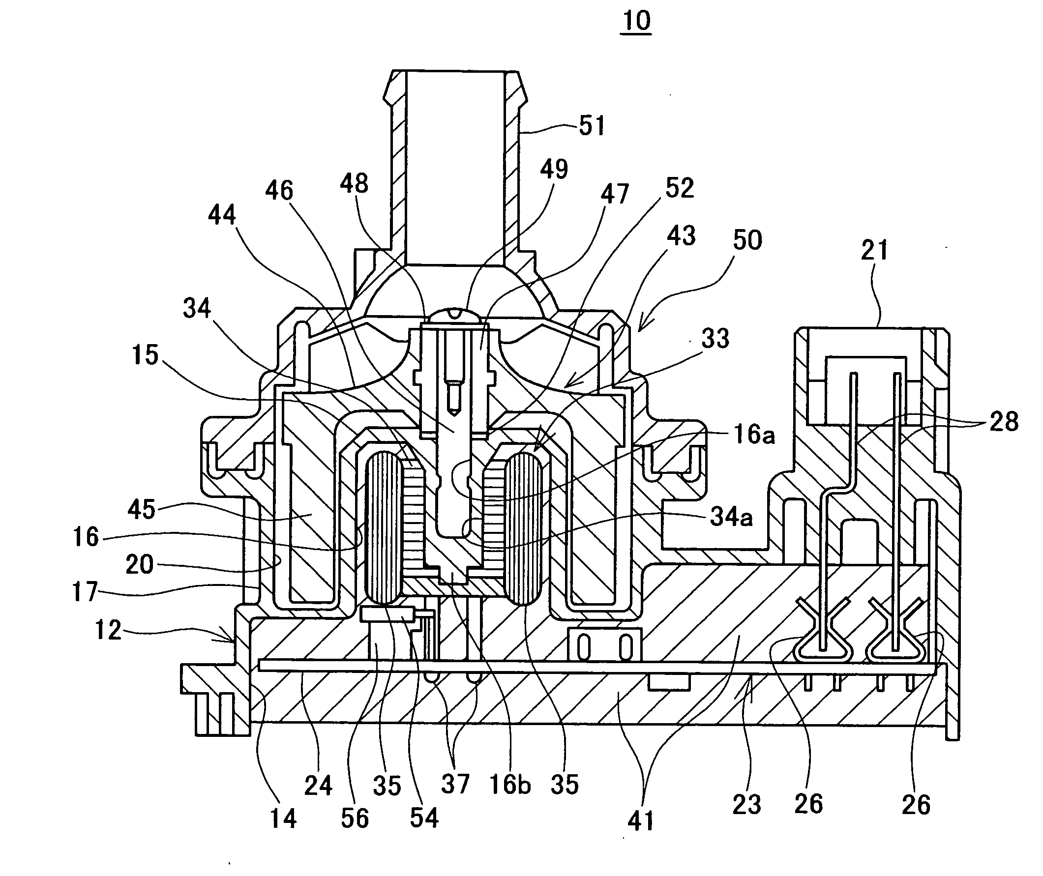
[0020]An electric pump 10 according to the first representative embodiment will be explained with reference to the drawings. The electric pump 10 may be used to circulate cooling water to cool the engine of an automobile, and be installed in the engine room of the automobile.

[0021]As shown in FIG. 1, the electric pump 10 includes a lower body 12 and an upper body 50 fixed to the lower body 12. Each of the lower body 12 and the upper body 50 may be formed integrally from a material such as resin. A cylindrical shaped protrusion 15 is formed in the top of the lower body 12 (on the left side in the figure). A shaft installation hole 16a is provided in the center of the protrusion 15. The lower end of a shaft 46 is fixed in the shaft installation hole 16a. The top end of the shaft 46 projects higher than the top surface of the protrusion 15. An impeller 43 is rotatably attached to the top end of the shaft 46.

[0022]An external wall 17 is formed in a cylindrical shape around the protrusio...

second embodiment

[0040]Next, the electric pump 100 according to a second representative embodiment is explained. The electric pump 100 may also be used to circulate cooling water to cool the engine of an automobile.

[0041]As shown in FIG. 3, the electric pump 100 includes a lower body 110, an upper body 150 fixed to the top end of the lower body 110, and a lid 170 fixed to the bottom end of the lower body 110. A cylindrical shaped protrusion 115 is formed in the top of the lower body 110. An external wall 118 is formed in a cylindrical shape around the protrusion 115. The protrusion 115 and the external wall 118 are disposed concentrically. A cylindrical portion 145 of an impeller 143 is housed between the protrusion 115 and the external wall 118.

[0042]A bearing installation hole 117 is provided in the center of the protrusion 115, and a bearing 162 is installed in the bottom of the bearing installation hole 117. A bottom end 146b of a hollow shaft 146 is inserted into the bearing 162. The bearing 16...


PUM


Abstract

An electric pump may comprise a pump case (110, 150) having a pump chamber. An impeller 143 may be rotatably disposed within the pump chamber. The impeller 143 may include a magnetized cylindrical portion 145. A stator 133 may be disposed opposite to the cylindrical portion 145 of the impeller 143. The stator 133 may drive the impeller 143 by applying magnetic forces to the cylindrical portion 145 of the impeller 143. A shaft 146 may be formed integrally with the impeller 143. One end of the shaft 143 may be rotatably supported with respect to the pump case.

Description

CROSS-REFERENCE TO RELATED APPLICATION[0001]This application claims priority to Japanese Patent Application numbers 2006-22284, filed on 31 January with the JPO, the contents of which are hereby incorporated by reference into the present application.BACKGROUND OF THE INVENTION[0002]1. Field of the Invention[0003]The present invention relates to an electric pump used to circulate cooling water to cool an automobile engine or an inverter or the like.[0004]2. Description of the Related Art[0005]The known electric pump includes a pump case. A pump chamber is formed in the pump case. An impeller is disposed within the pump chamber. The impeller includes a magnetized cylindrical portion. A bearing is formed integrally in the center of the impeller, and a shaft is inserted into the bearing. One end of the shaft is fixed in the pump casing (in other words, the shaft is supported cantilevered from the pump case). A stator is disposed outside the pump case to drive the impeller. The external ...

Claims


Application Information

Patent Timeline
IPC IPC(8): F04B17/00
CPCF04D13/0673F04D29/047F04D29/0413F04D13/0606
Inventor NAKAMICHI, KAZUTAKAGAMO, MASARUKOBAYASHI, MASAHIROTAGUCHI, ATSUSHI
Owner AISAN IND CO LTD
Why Eureka
Try Eureka