Charging controller for performing constant current and voltage modes

a charging controller and constant current technology, applied in the field of charging controllers, can solve the problems of damage to the device and unsafe charging, and achieve the effect of preventing damage to the charged devi

Active Publication Date: 2007-09-13
SAMSUNG ELECTRONICS CO LTD
View PDF3 Cites 19 Cited by
  • Summary
  • Abstract
  • Description
  • Claims
  • Application Information

AI Technical Summary

Benefits of technology

[0030]In this manner, because a pull-down current source is not coupled to the control node, the charging current to the charged device is maintained to be substantially zero during the constant voltage mode. Thus, the voltage at the charged device is not increased after the charged device is completely charged for preventing damage to the charged device.

Problems solved by technology

Such increased charging voltage Vz may damage the device Z such that charging is not performed safely.

Method used


Image

  • Charging controller for performing constant current and voltage modes
  • Charging controller for performing constant current and voltage modes
  • Charging controller for performing constant current and voltage modes

Examples


Embodiment Construction

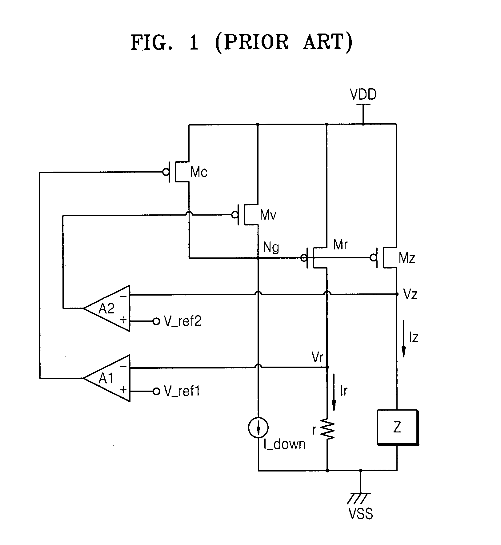
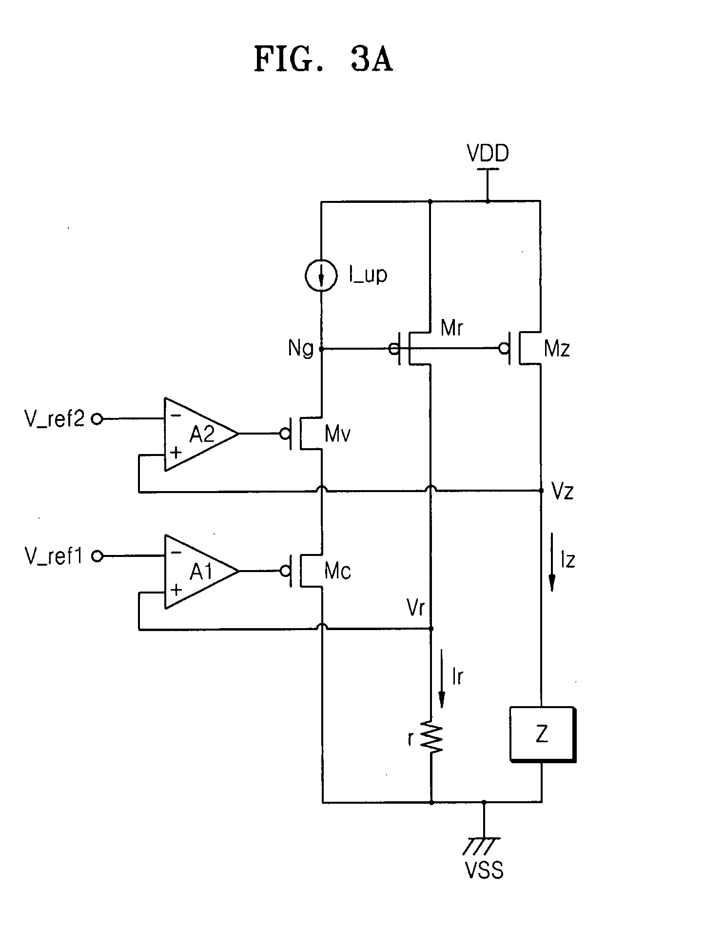
[0038]FIGS. 3A, 3B, and 3C show circuit diagrams with each illustrating a respective charging controller according to embodiments of the present invention. Each of the charging controllers of FIGS. 3A, 3B, and 3C includes first and second power transistors Mz and Mr, a device Z (such as a battery for example) that is to be charged, a programmable resistor r as an example reference device, a pull-up current source I_up, a first amplifier A1, a second amplifier A2, a first control transistor Mc, and a second control transistor Mv. The first and second control transistors Mc and Mv are example feedback controlled devices.

[0039]In one embodiment of the present invention, the power transistors Mr and Mz are implemented with PMOSFETs (P-channel metal oxide field effect transistors). However, the present invention may also be practiced with the power transistors Mr and Mz being implemented with NMOSFETs (N-channel metal oxide field effect transistors).

[0040]The sources of the first and sec...


PUM


Abstract

A charging controller includes a control node having a control voltage generated thereon for controlling a first current to a charged device and a second current to a reference device. Feedback loops are formed with amplifiers and a pull-up current source and control transistors, or with amplifiers and transfer transistors, for maintaining the second current at a constant current level during a constant current mode and for maintaining a voltage of the charged device at a constant voltage level during a constant voltage mode. Use of a pull-down current source at the control node is avoided for preventing damage to the charged device.

Description

BACKGROUND OF THE INVENTION[0001]This application claims priority under 35 USC §119 to Korean Patent Application No. 2006-21955, filed on Mar. 8, 2006 in the Korean Intellectual Property Office, the disclosure of which is incorporated herein in its entirety by reference.[0002]1. Field of the Invention[0003]The present invention relates generally to chargers such as battery chargers, and more particularly, to a charging controller that maintains a charging voltage to be constant during a constant voltage mode.[0004]2. Background of the Invention[0005]As use of portable electronic devices, such as cellular phones, personal digital assistants (PDAs), portable multimedia players (PMPs), etc., increases, various techniques for charging batteries safely and efficiently are being developed. In portable electronic devices, secondary batteries, which can be re-charged when discharged, such as lithium ion batteries, are used.[0006]FIG. 1 is a circuit diagram of a conventional charging control...

Claims


Application Information

Patent Timeline
Patent Type & Authority Applications(United States)
IPC IPC(8): H02J7/00
CPCH02J7/0077H02J7/00712H02J7/04
Inventor CHOI, JONG-SANGLEE, JIN-KUG
Owner SAMSUNG ELECTRONICS CO LTD
Why Eureka
Try Eureka