Liquid crystal panel, liquid crystal display device and terminal device

a liquid crystal display and terminal device technology, applied in non-linear optics, instruments, optics, etc., can solve the problems of poor image visibility, poor display quality, and poor contrast level, and achieve excellent display performance, suppress the phenomenon, and high quality

Active Publication Date: 2007-09-27
NEC LCD TECH CORP
View PDF19 Cites 65 Cited by
  • Summary
  • Abstract
  • Description
  • Claims
  • Application Information

AI Technical Summary

Benefits of technology

[0053]The present invention has been done in consideration of such a problem. Therefore, it is an object of the present invention to provide a liquid crystal panel capable of achieving an excellent display performance using a circular polarizing plate, and a liquid crystal display device and terminal device using the same, in particular, with respect to a semi-transmission type liquid crystal display device in a horizontal electric field mode (In-Plane Switching: IPS) mode.
[0054]In order to achieve the above object, a liquid crystal panel according to the present invention, comprises a backside substrate, a viewer-side substrate, and a liquid crystal layer disposed in between both of substrates, in which a pixel area includes a reflective display area where a light from a viewer side is reflected and a transmissive display area where a light from the backside is transmitted. The liquid crystal panel of which the liquid crystal layer at least in the transmissive display area is driven by a horizontal electric field when a voltage is applied in parallel to a surface of the substrate, in which the liquid crystal layer has anisotropy of a refractive index in a display surface, has a circular polarizing plate individually disposed outside of each the backside substrate and the viewer-side substrate, and a compensator having a function of reducing the refractive index anisotropy of the liquid crystal layer which is disposed in at least either one of intervals between the circular polarizing plates and respective substrates.
[0055]According to this liquid crystal panel, by disposing a compensator for counteracting anisotropy of refractive index in a display surface of a liquid crystal layer, it is possible to achieve a semi-transmission type liquid crystal panel in IPS mode which is capable of appropriate display even using a circular polarizing plate. That is, even if a circular polarizing plate is applied to a semi-transmission type liquid crystal panel in IPS mode, displays can be in a normally black mode both in a transmissive display area and a reflective display area. Further, an excellent viewing angle characteristic can be achieved because a liquid crystal layer is driven by the horizontal electric field. In addition, the viewing angle characteristic can be prevented from becoming worse due to the refractive index anisotropy because the compensation plate operates to counteract the refractive index anisotropy of the liquid crystal layer.

Problems solved by technology

However, liquid crystal panels in these two modes have a narrow viewing angle for viewing in proper grayscale, and grayscale inversion occurs outside of the optimal viewing angle.
However, the terminal devices come to display a lot of image information other than the characters under the recent technical development, and it becomes a problem that the grayscale inversion leads to very poor image visibility.
The reflection type can achieve low power consumption because it can use external light, however, this type is inferior to the transmission type in display quality such as a contrast level.
Further, when a voltage is applied between the pixel electrode and the common electrode, birefringence of the liquid crystal layer in the transmissive display part varies, which causes a light to emerge, and a display becomes white.
However, a fine display cannot be accomplished by merely applying a circular polarizing plate to the above described conventional semi-transmission type liquid crystal display panels in horizontal electric field mode.
Accordingly, a black display cannot be achieved due to variation of circular polarization state.
Accordingly, black displays cannot be achieved.
As described above, it has turned out that the conventional semi-transmission type liquid crystal display panels in the horizontal electric field modes cannot accomplish fine displays by merely applying circular polarizing plates.
Therefore, though a circular polarizing plate improves significantly in its quality, as described in Non-Patent Document 3, there remains a problem where appropriate display cannot be achieved even if the circular polarizing plate adopted in the conventional semi-transmission type liquid crystal display device in the vertical alignment mode is applied to the conventional semi-transmission type liquid crystal display device in the horizontal electric field drive mode.

Method used


Image

  • Liquid crystal panel, liquid crystal display device and terminal device
  • Liquid crystal panel, liquid crystal display device and terminal device
  • Liquid crystal panel, liquid crystal display device and terminal device

Examples


first embodiment

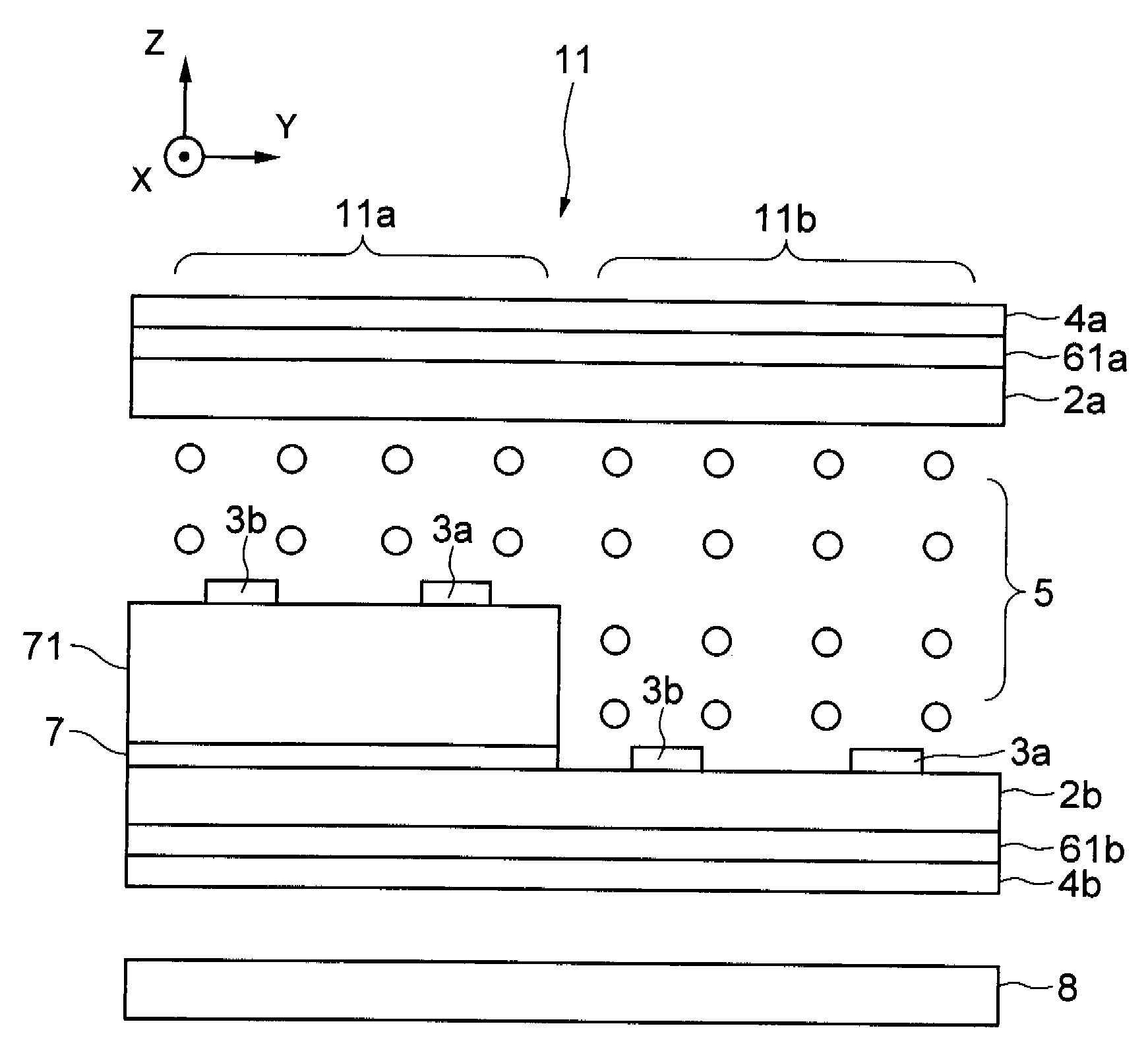
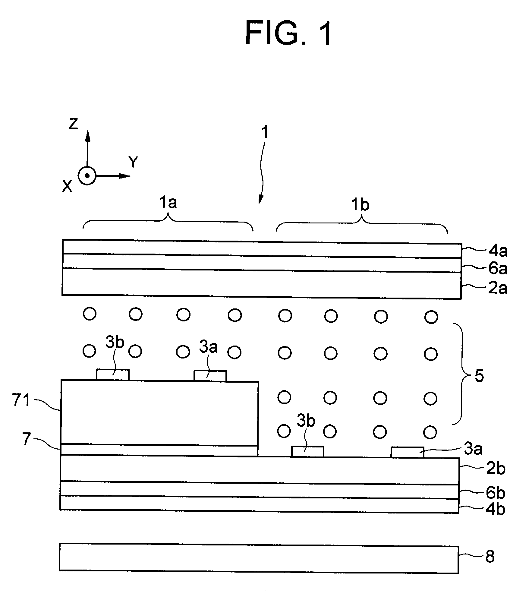
[0107]As shown in FIG. 1, the liquid crystal display device 1 comprises a viewer-side substrate 2a, a backside substrate 2b, and a liquid crystal layer 5 which is sandwiched in between both of substrates 2a and 2b, wherein a pixel area has a reflective display area 1a in which a light from a viewer-side is reflected and a transmissive display area 1b in which a light from a backside is transmitted, and the liquid crystal layer 5 in the reflective display area 1a and the transmissive display area 1b is driven by a horizontal electric field when a voltage is applied in parallel to the substrate surface.

[0108]The viewer-side substrate 2a and the backside substrate 2b has circular polarizing plates respectively outer sides thereof, a viewer-side circular polarizing plate 4a and a backside circular polarizing plate 4b, and a viewer-side compensation plate 6a and a backside compensation plate 6b, which are compensation plates reducing a refractive index anisotropy of the liquid crystal l...

fifth embodiment

[0174]As described, according to the liquid crystal display device 15 of the present embodiment, the thickness of the liquid crystal layers 51 are even in the transmissive display area 15b and the reflective display area 15a, so that when the refractive index anisotropy of the liquid crystal layer 51 in the transmissive display area 15b is counteracted, the refractive index anisotropy of the liquid crystal layer 51 in the reflective display area 15a is also counteracted. Other structures in the present embodiment than the above are the same as ones of the

[0175]The liquid crystal display device 15 of the present embodiment applies the liquid crystal layer 51 having a twist state in the primary orientation to prevent variations of birefringence due to thickness variations of the liquid crystal layer 51 caused by variation of manufacturing processes, which realizes a good compensation. That is, the liquid crystal layer 5 of the fifth embodiment have an uniaxial orientation in a certain...

ninth embodiment

[0190]On the contrary, when the compensation layer is formed into an in-cell type as in the ninth embodiment, the axis of the compensation layer can be controlled by employing the conventional orientation method of the liquid crystal layer. Therefore, high axial precision can be achieved with the minimum control. Further, it is possible to arrange the compensation layer closely to the liquid crystal layer, so that a high-quality display can be achieved by reducing the disturbance of the polarized light.

[0191]Meanwhile, the circular polarizing plate has a larger margin for the axial shift compared to the compensator. That is, the circular polarizing plate that has a larger margin is preferable to be placed on the outer side. In particular, when the polarizing plate is formed into an in-cell type, there are more issues to be overcome than the case of forming the compensator into an in-cell type, such as securing the high degree of polarization, liquid crystal panel process resistance,...


PUM

PropertyMeasurementUnit
angleaaaaaaaaaa
angleaaaaaaaaaa
angleaaaaaaaaaa

Abstract

To provide a liquid crystal panel capable of realizing excellent display performance using a circular polarizing plate therein, and a liquid crystal display device and a terminal device using the same, with respect to a semi-transmission type liquid crystal display device in a horizontal electric field mode (In-Plane Switching: IPS).A viewer-side circular polarizing plate and a backside circular polarizing plate are disposed outside of a viewer-side substrate and a backside substrate respectively, and a viewer-side compensation plate and a backside compensation plate are disposed between the respective polarizing plates and substrates to reduce a refractive index anisotropy of a liquid crystal layer.

Description

FIELD OF THE INVENTION[0001]The present invention relates to a liquid crystal panel, a liquid crystal display device and terminal device, in particular, a liquid crystal panel, a liquid crystal display device and terminal device having a reflective display area which reflects incident external light to display and a transmissive display area which transmits light from the backside to display, wherein at least the display area of a transmitting-type is driven by a horizontal electric field.DESCRIPTION OF THE RELATED ART[0002]Recently, the liquid crystal display device, having the advantage of thin, light-weight, small and low power consumption, is widely installed in and used for large size terminal devices such as monitors and televisions, middle size terminal devices such as laptop computers, cash dispensers, and vending machines, and small size terminal devices such as PDAs (Personal Digital Assistance), mobile telephones, and portable game devices.[0003]A liquid crystal panel, wh...

Claims


Application Information

Patent Timeline
Patent Type & Authority Applications(United States)
IPC IPC(8): G02F1/1335G02F1/1343
CPCG02F1/133555G02F1/133634G02F1/133636G02F2413/14G02F2001/133541G02F2001/134372G02F2413/13G02F1/134363G02F1/133541G02F1/134372
Inventor UEHARA, SHINICHIMATSUSHIMA, JINSUMIYOSHI, KEN
Owner NEC LCD TECH CORP
Why Eureka
Try Eureka