Accommodative intraocular lens system

a technology of intraocular lens and iol, which is applied in the field of intraocular lens, can solve the problems of deteriorating vision, increasing the difficulty of use, and natural lens prone to flattening

a technology of intraocular lens and iol, which is applied in the field of intraocular lens, can solve the problems of deteriorating vision, increasing the difficulty of use, and natural lens prone to flattening

US20070260308A1Inactive Publication Date: 2007-11-08NOVARTIS AG

Image

  • Accommodative intraocular lens system
  • Accommodative intraocular lens system
  • Accommodative intraocular lens system

Examples


Embodiment Construction

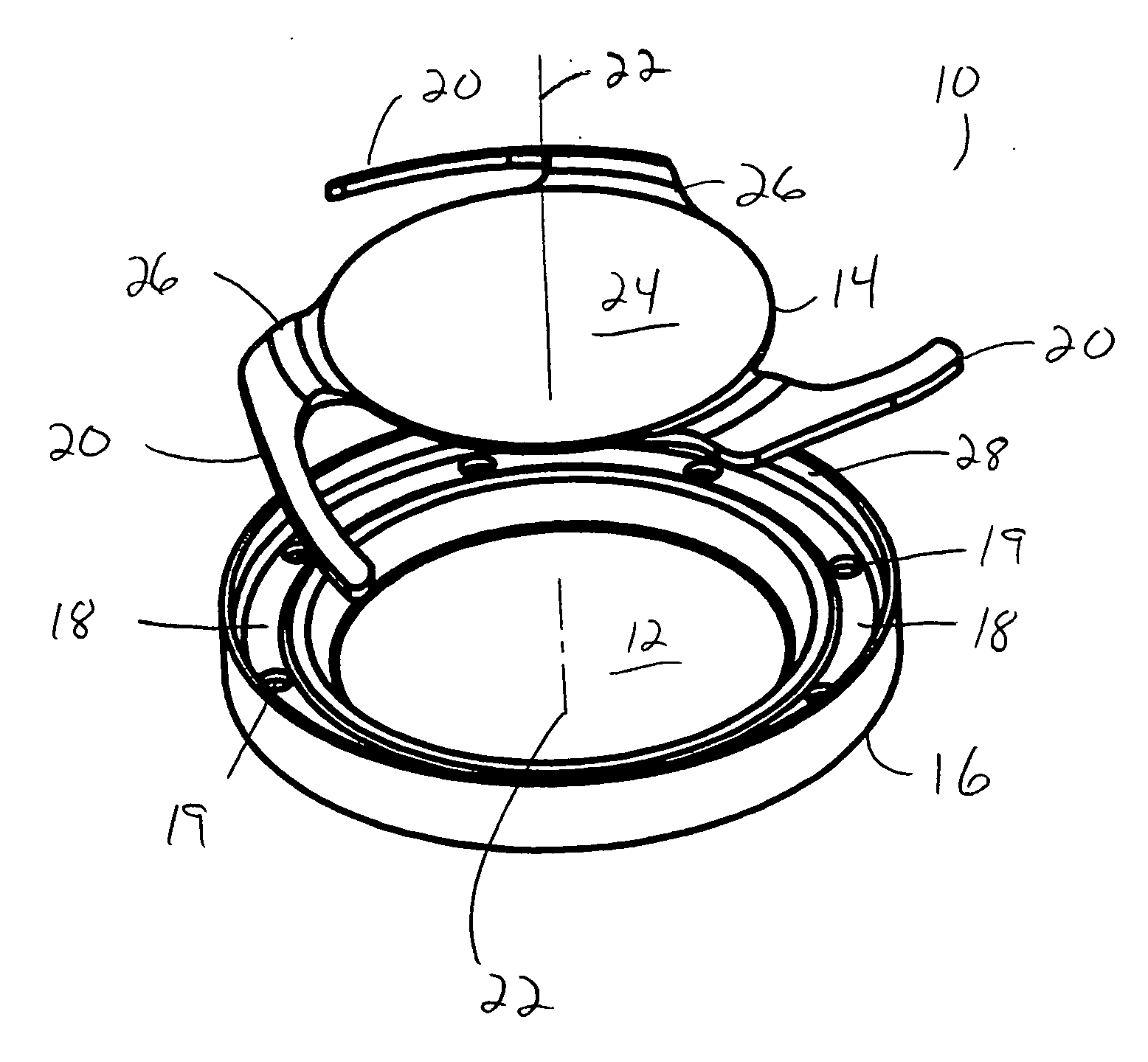
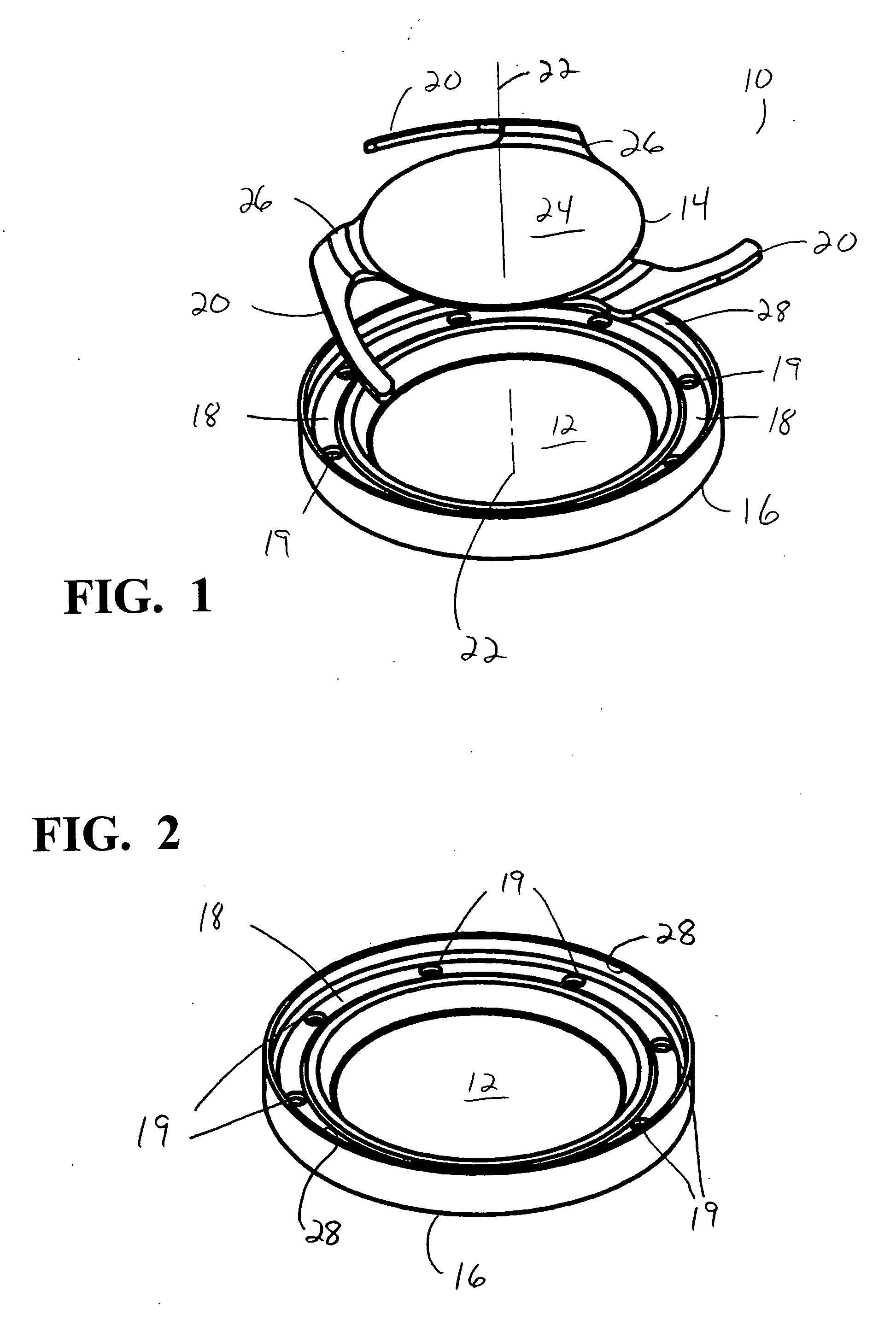
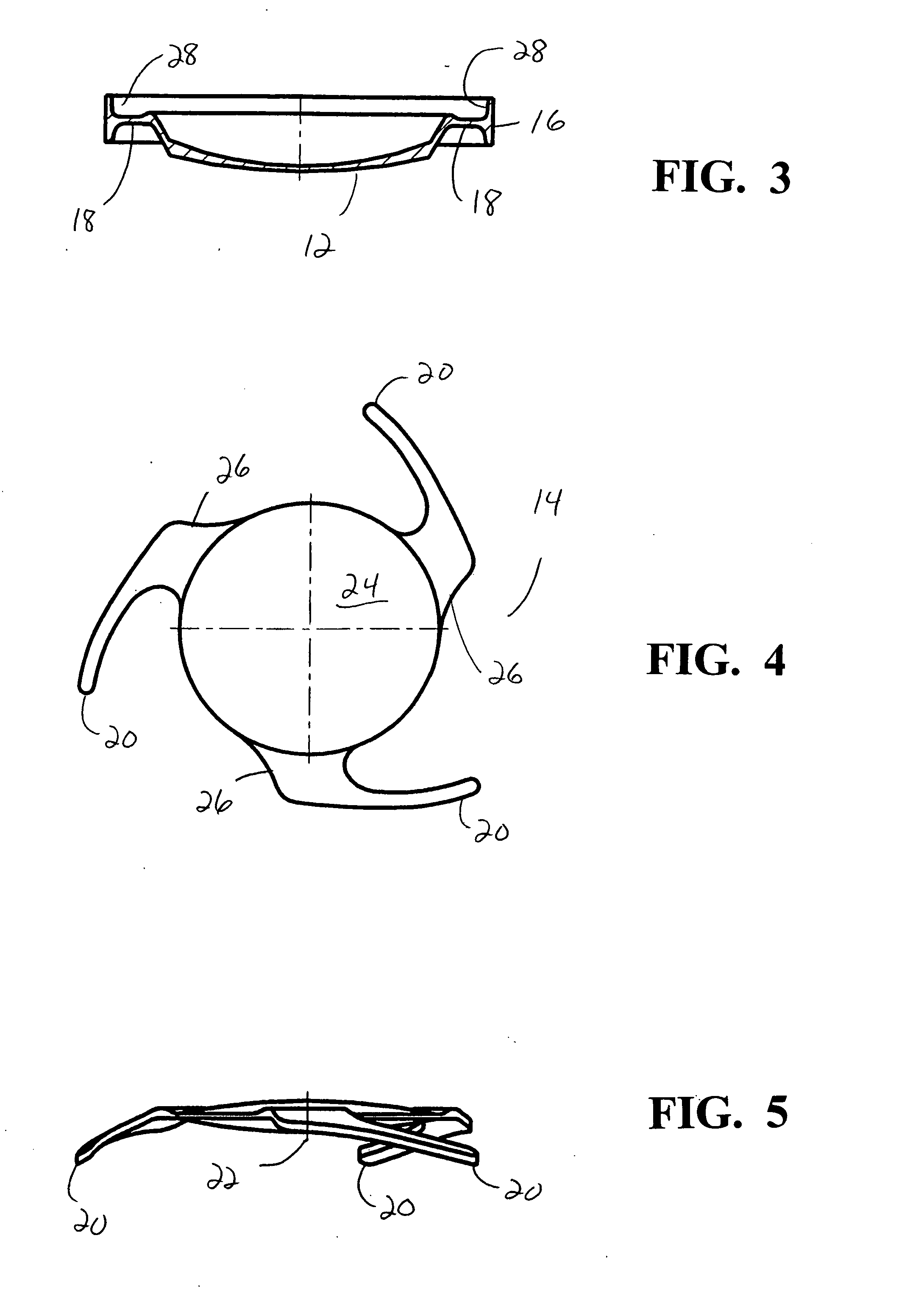
[0022] As best seen in the figures, lens system 10 of the present invention generally consists of posterior lens 12, anterior lens 14 and circumferential ring 16. Lens 12 is preferably integrally formed with ring 16. Lens 12 preferably is made from a soft, foldable material that is inherently resistive to the formation of PCO, such as a soft acrylic. Lens 14 preferable is made from a soft, foldable material such as a hydrogel, silicone or soft acrylic. Lens 12 may be any suitable power, but preferably has a negative power. Lens 14 may also be any suitable power but preferably has a positive power. The relative powers of lenses 12 and 14 should be such that the axial movement of lens 14 toward or away from lens 12 should be sufficient to adjust the overall power of lens system 10 at least one diopter and preferably, at least three to four diopters, calculation of such powers of lenses 12 and 14 being within the capabilities of one skilled in the art of designing ophthalmic lenses by,...


PUM


Abstract

A two-optic accommodative lens system. The first lens has a negative power and is located posteriorly within the capsular bag and lying against the posterior capsule. The periphery of the first lens is attached to a ring-like structure having a side wall. The second lens is located anteriorly to the first lens within of the capsular bag and is of a positive power. The peripheral edge of the second lens contains a plurality of haptics that are arranged in a spiral pattern and project posteriorly from the second lens and toward the first lens. The haptics are relatively firm, yet still flexible and ride within the side wall of the ring-like structure, so that flattening or steepening of the capsule in reaction to movement of the ciliary muscle and corresponding shrinkage of the capsular bag causes the second lens to move along the optical axis of the lens system.

Description

BACKGROUND OF THE INVENTION [0001] This invention relates generally to the field of intraocular lenses (IOL) and, more particularly, to accommodative IOLs. [0002] The human eye in its simplest terms functions to provide vision by transmitting light through a clear outer portion called the cornea, and focusing the image by way of a crystalline lens onto a retina. The quality of the focused image depends on many factors including the size and shape of the eye, and the transparency of the cornea and the lens. [0003] When age or disease causes the lens to become less transparent, vision deteriorates because of the diminished light which can be transmitted to the retina. This deficiency in the lens of the eye is medically known as a cataract. An accepted treatment for this condition is surgical removal of the lens and replacement of the lens function by an artificial intraocular lens (IOL). [0004] In the United States, the majority of cataractous lenses are removed by a surgical techniqu...

Claims


Application Information

Patent Timeline
08 Nov 2007
Publication
US20070260308A1
IPC
A61F2/16
CPC
A61F2/1613; A61F2/1629; A61F2250/0053; A61F2002/1681; A61F2/1648; A61F2/14; A61F2/00
Inventors
TRAN, SON TRUNG