

Conditional Access System
a technology of access system and access control, applied in the field of access control system, can solve the problems of inherent inefficiency and waste of power, and achieve the effect of saving power
- Summary
- Abstract
- Description
- Claims
- Application Information
AI Technical Summary
Benefits of technology
Problems solved by technology
Method used
Image

Examples
Embodiment Construction
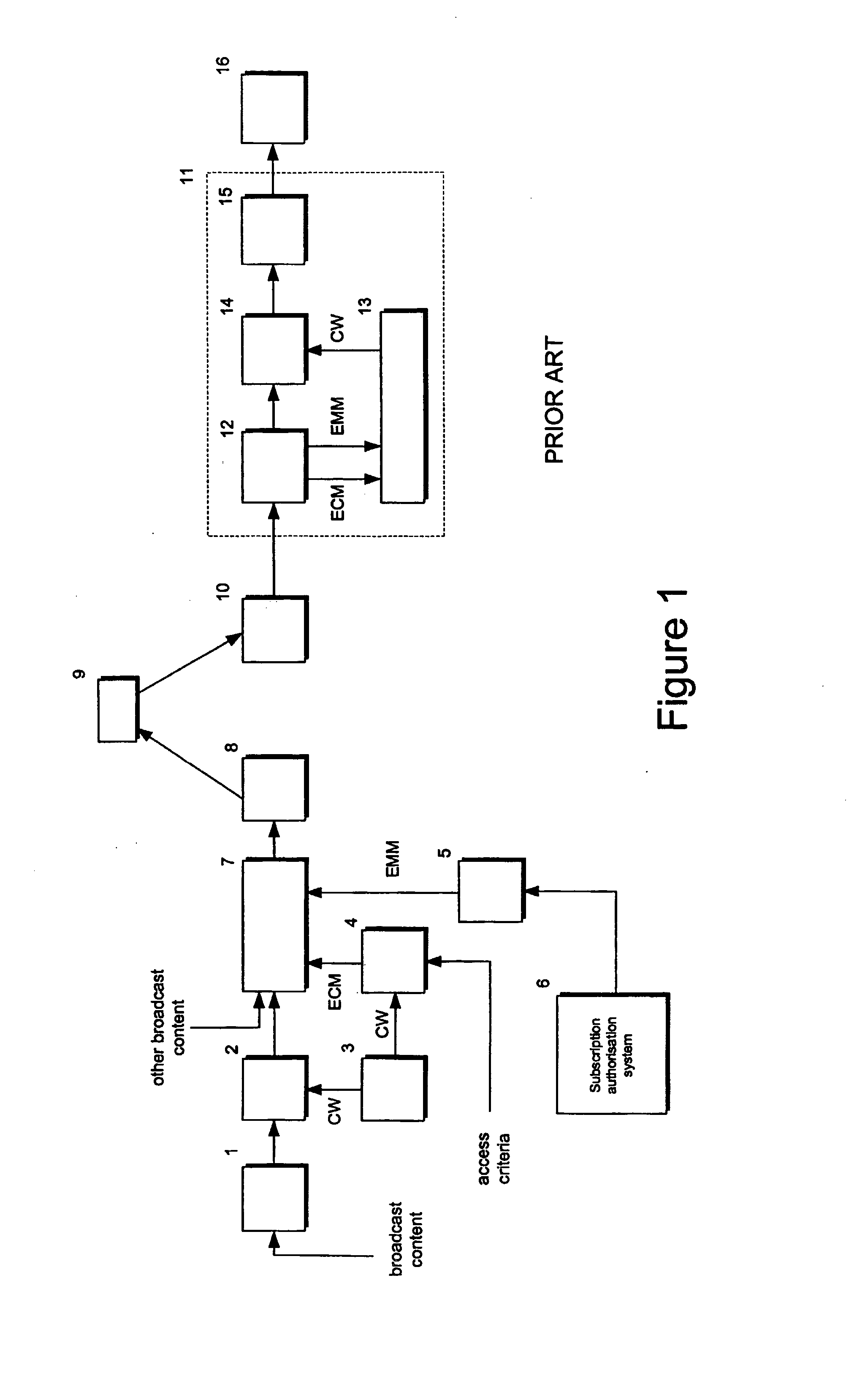
[0031] Referring to FIG. 1, in a conventional conditional access system, content to be broadcast, including for example, video, audio and data components, is encoded in an encoder 1 using an appropriate coding system, for example MPEG-2 for digital broadcasting. The encoded broadcast stream is scrambled in a scrambler 2 under the control of a control word CW generated by a control word generator 3 in a manner which is well-known per se. The control word is encrypted into an Entitlement Control Message (ECM) by an ECM generator 4 together with access criteria which identify the service and the conditions required to access the service. For example, the access criteria may specify regional limitations on the broadcast. A further type of message, referred to as an Entitlement Management Message (EMM), which carries details of the subscriber and his subscription is generated by an EMM generator 5 based on subscription information received from a subscription authorisation system 6. Whil...
PUM
 Abstract
Description
Claims
Application Information