Driving device and scanner

Active Publication Date: 2007-12-13
BROTHER KOGYO KK
View PDF4 Cites 7 Cited by
  • Summary
  • Abstract
  • Description
  • Claims
  • Application Information

AI Technical Summary

Benefits of technology

[0021]The objective of the present invention is to provide a compact driving device that allows the scanning member be moved precisely along the scanning direction. To achieve such objective, the following technique is taught in the present specification.
[0023]In the driving device described above, the pinion and the first gear are disposed at the same level in the orthogonal direction with respect to the frame. Further, the surface of the motor housing in contact with the motor side surface of the frame is within a more nearing range of level in the orthogonal direction with respect to the frame to the first gear than the surface of the second gear facing the gear side surface of the frame. The driving device can be assembled much compactly in comparison with the generally known driving devices. With the driving device being much compact, especially in the orthogonal direction with respect to the frame, the length of the shafts can be shortened, thus the trembling of the shafts are reduced. When such driving device is incorporated into a scanner for driving the scanning member, the trembling transmitted to the scanning member is reduced. It allows the scanning member to scan precisely.

Problems solved by technology

The trembling transmitted to the belt causes the movement of the scanning member to sway in an inappropriate direction.

Method used


Image

  • Driving device and scanner
  • Driving device and scanner
  • Driving device and scanner

Examples


Embodiment Construction

[0030]The embodiment of the present invention will be described in detail below with reference to the figures.

(1. The Overall Configuration)

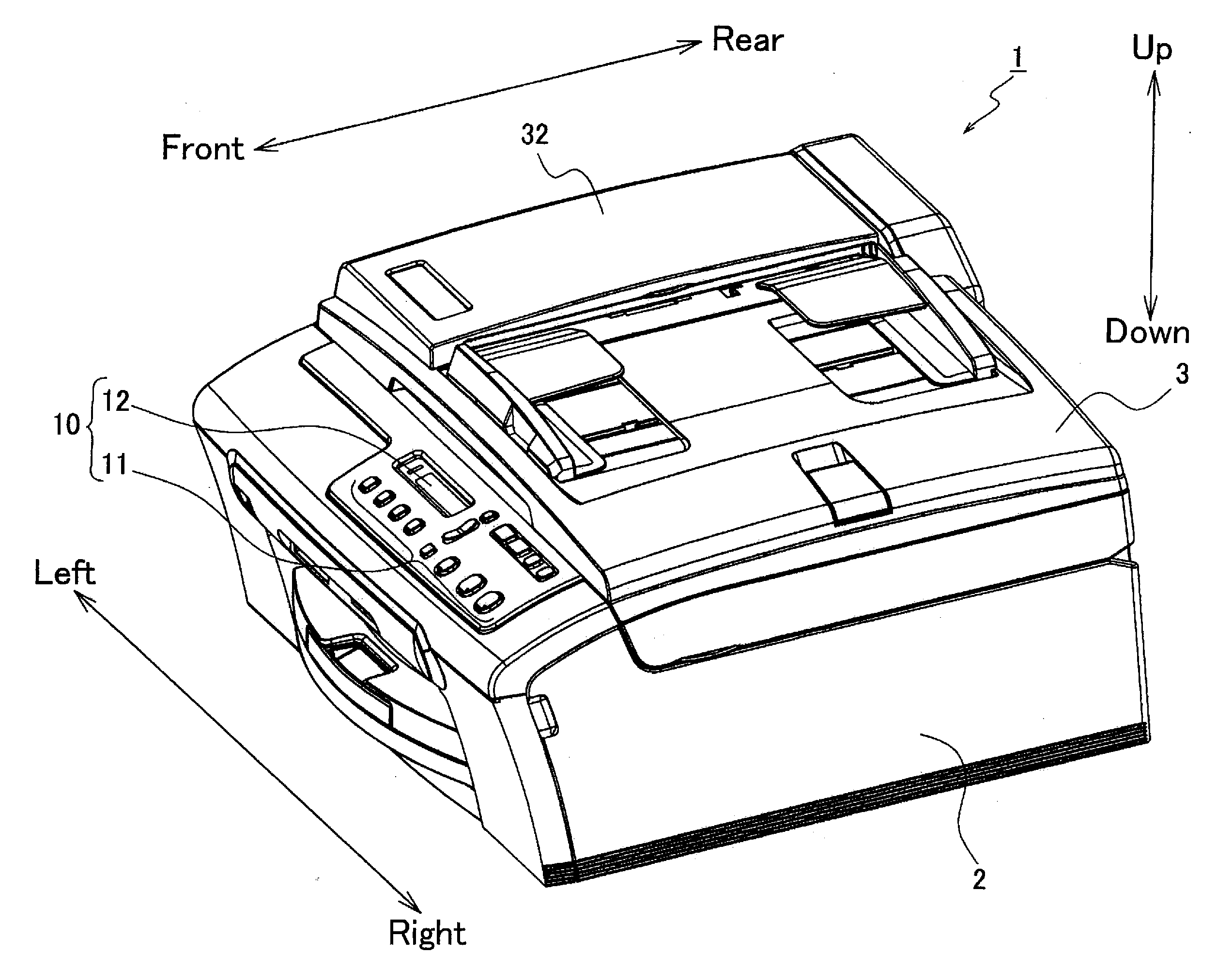
[0031]FIG. 1 shows a perspective view of a multi-function device 1 of the present embodiment.

[0032]The multi-function device 1 of the present embodiment comprises printing function, as well as functions such as scanning function, color copying function, facsimile function, etc. As shown in FIG. 1, the multi-function device 1 has a main body 2 made of synthetic resin. The main body 2 is rectangular and parallelepiped.

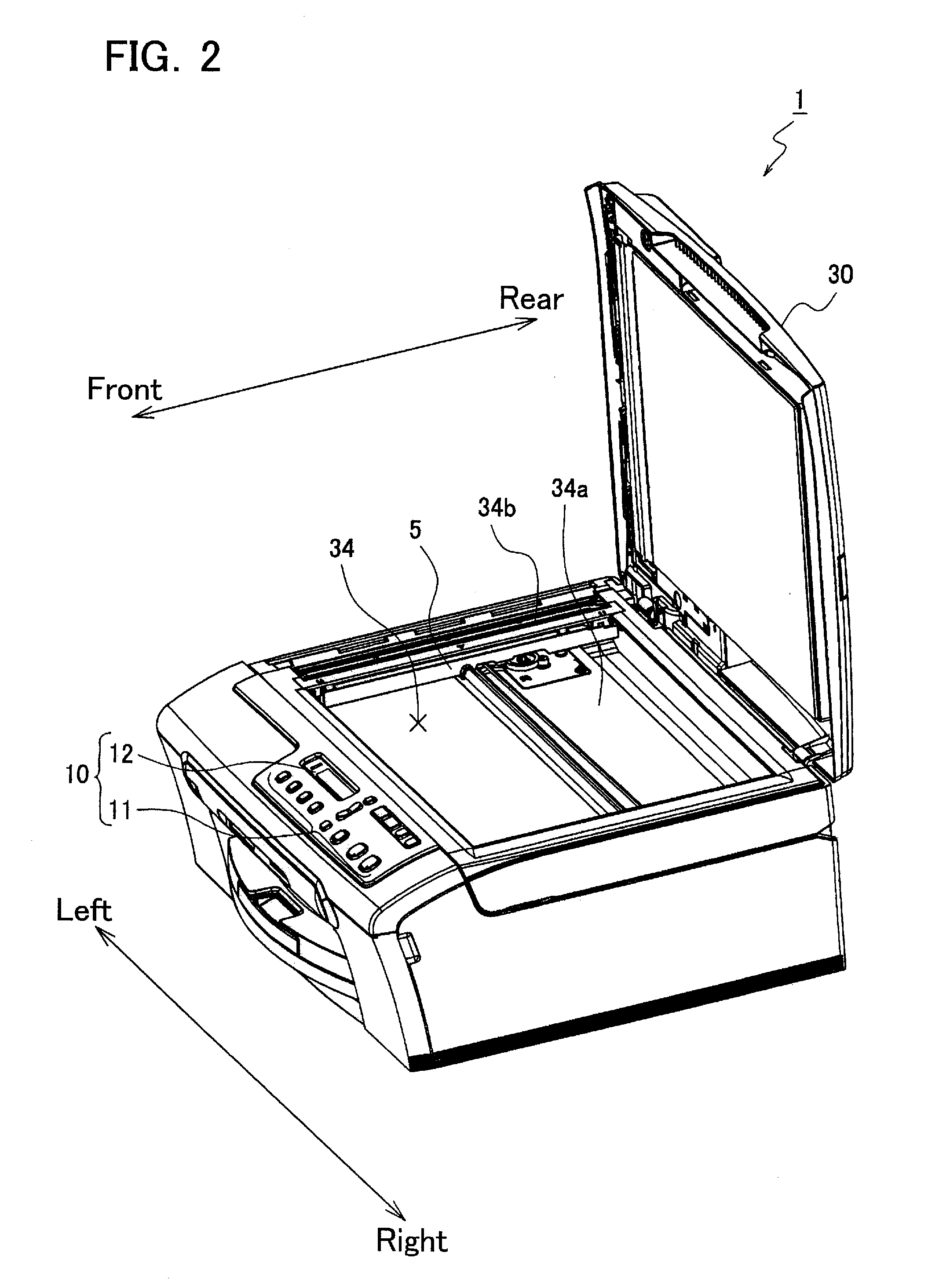
[0033]On the top surface of the front part of the multi-fuinction device 1, an operation panel 10 is disposed. The operation panel 10 includes buttons 11 for inputting operation commands and a display monitor 12 (for example, a LCD) to display messages and images. At the rear side of the operation panel 10, a scanner unit 3 is disposed. The scanner unit 3 is used to scan images from documents. The scanner unit 3 is utilized to enforc...


PUM


Abstract

The driving device is provided with a motor, a pinion, a first gear, a second gear, and a frame. The frame has a motor side surface and a gear side surface, and includes a first portion and a second portion. A motor housing of the motor is fixed to and supported at the motor side surface of the first portion. A motor shaft extends from the motor housing, penetrating the first portion from the motor side surface to the gear side surface. The pinion is fixed to the distal end of the motor shaft at the gear side surface. The first gear and the second gear are coaxially disposed and rotatably supported at the gear side surface of the second portion. The driving force of the motor is transmitted to the first gear and the second gear through the pinion. The gear side surface of the second portion is offset toward the motor side than the motor side surface of the first portion.

Description

CROSS-REFERENCE TO RELATED APPLICATION[0001]This application claims priority to Japanese Patent Application No. 2006-050368, filed on Feb. 27, 2006, the contents of which are hereby incorporated by reference into the present application.BACKGROUND OF THE INVENTION[0002]1. Field of the Invention[0003]The present invention relates to a driving device utilized in a scanner and a scanner having such driving device.[0004]2. Description of the Related Art[0005]A scanner having a main body, a scanning member, a belt, and a driving device is known. In such scanner, the scanning member is installed inside the main body. A tempered glass is disposed on the top surface of the main body above the scanning member. The driving device moves the scanning member by driving the belt.[0006]FIG. 5 shows a typical type of a generally known driving device utilized in scanners. The driving device 100 includes a stepping motor 101, a metal frame 102, a motor shaft 103, and a pinion 104. The stepping motor ...

Claims


Application Information

Patent Timeline
IPC IPC(8): F16H1/32
CPCF16H1/20H04N1/00519H04N1/00549H04N1/103H04N1/1013H04N1/1026H04N1/00559
Inventor OSAKABE, YOSHINORI
Owner BROTHER KOGYO KK
Why Eureka
Try Eureka