Distribution switchgear

a technology of distribution switch and switch body, which is applied in the direction of substations, substations, non-enclosed substations, etc., can solve the problems of unsatisfactory user experience, and achieve the effects of saving maintenance labor, widening the protection range, and increasing reliability

Inactive Publication Date: 2008-01-10
HITACHI LTD
View PDF14 Cites 16 Cited by
  • Summary
  • Abstract
  • Description
  • Claims
  • Application Information

AI Technical Summary

Benefits of technology

[0008]Since the conventional distribution switchgear is compact and features good maintainability as a unit constituting distribution switchgear, it has been used in various systems. It has been found from its use in various systems that the distribution switchgear has to be improved in several points.
[0011]The present invention has been made based on the above circumstances and its object is to provide a distribution switchgear which not only protects the whole load side including a circuit breaker against ground faults to widen the protection range and thus increases reliability but also can achieve labor saving in maintenance and a longer service life.
[0012]To provide a distribution switchgear which protects the whole load side including a circuit breaker against ground faults to widen the protection range and thereby increases its reliability and can achieve labor saving in maintenance and longer service life.

Problems solved by technology

Besides, there is room for improvement to assure maintainability of a busbar connected with the distribution switchgear and extended service life of the distribution switchgear; therefore, it is not ideal for its user as the case stands now.

Method used


Image

  • Distribution switchgear
  • Distribution switchgear
  • Distribution switchgear

Examples


first embodiment

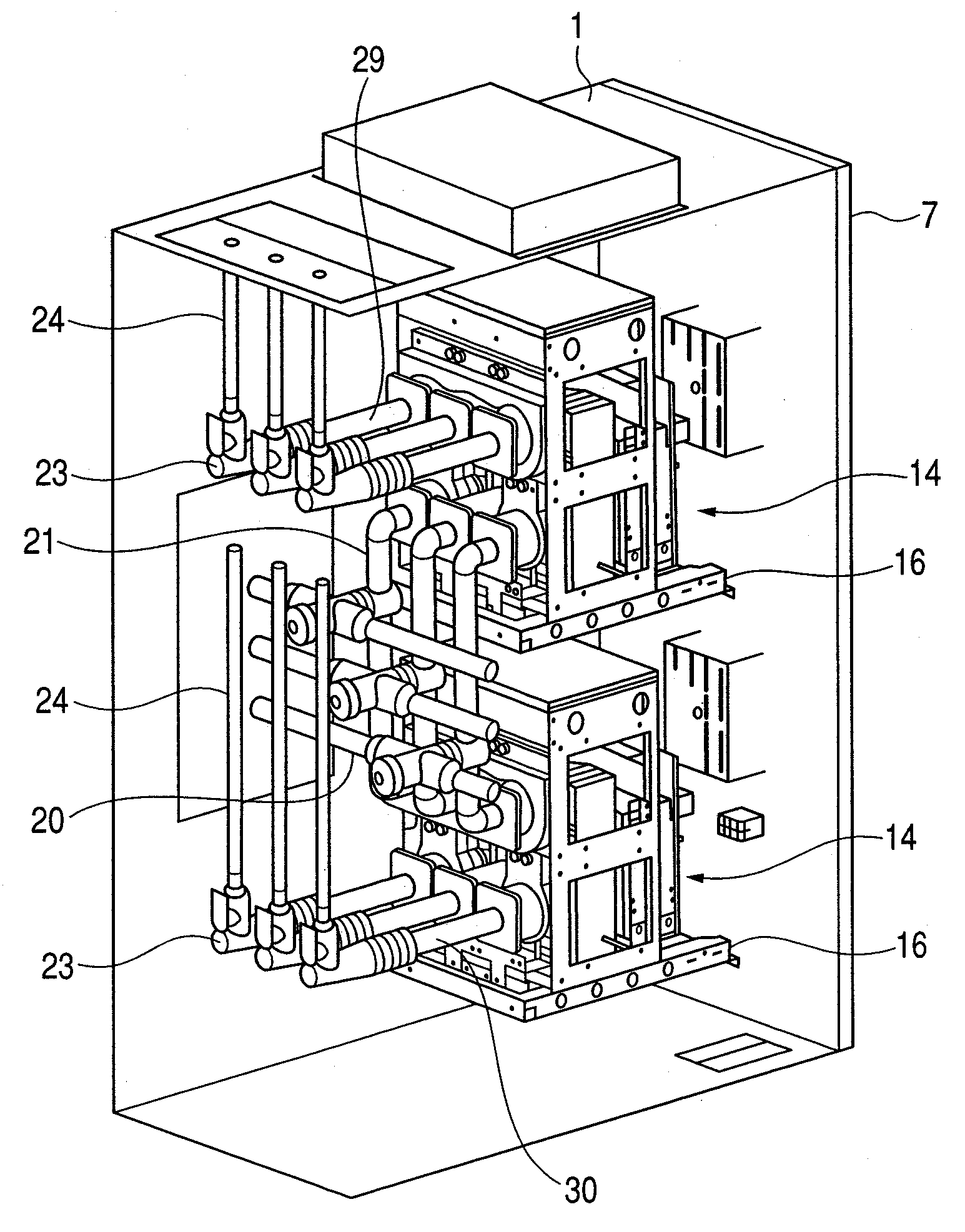
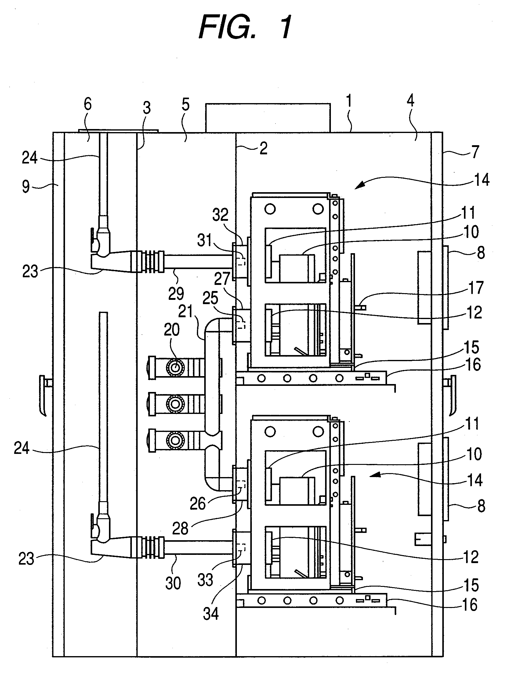
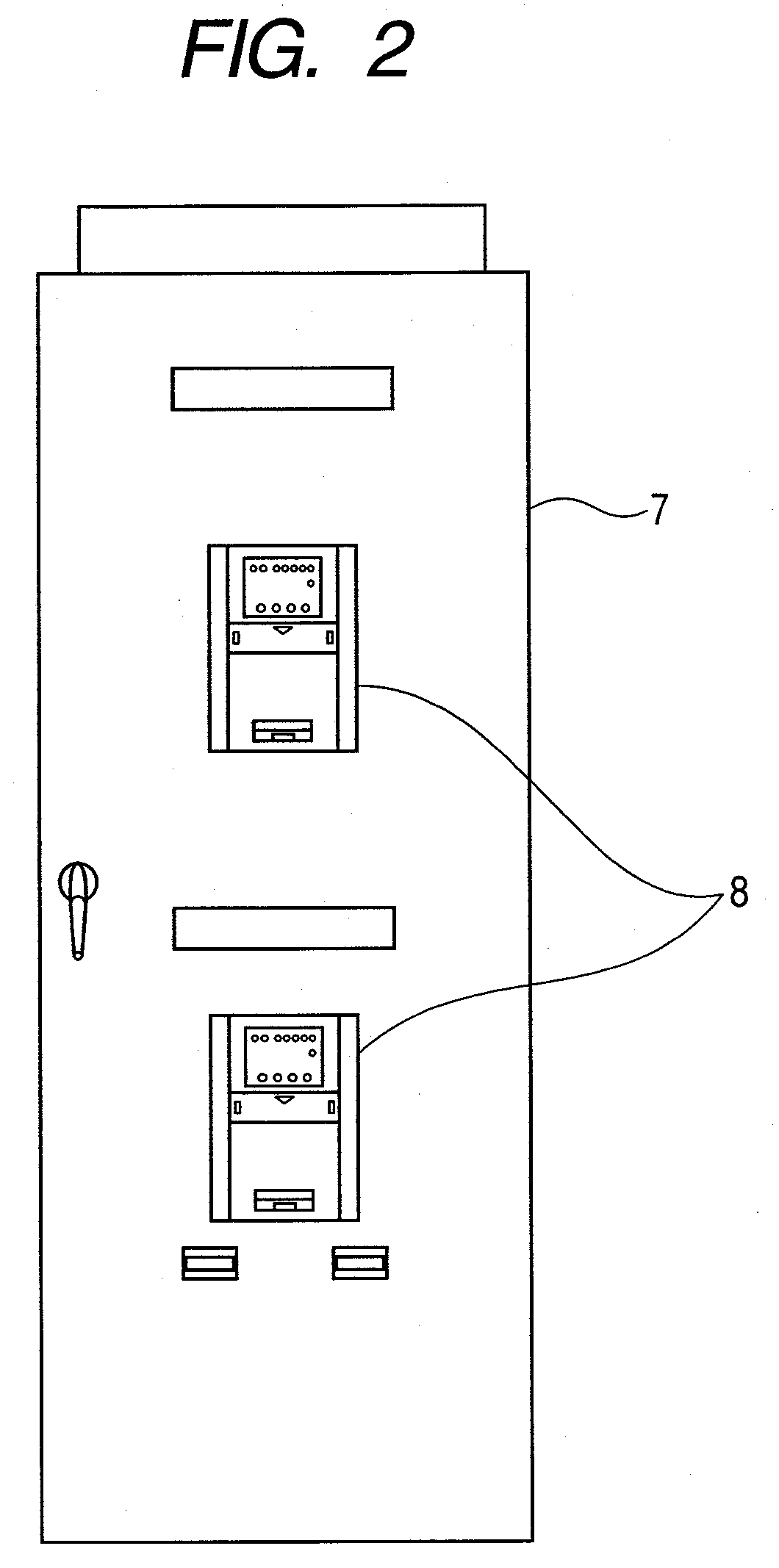
[0032]FIGS. 1 to 5 show distribution switchgear according to a first embodiment of the present invention, in which FIG. 1 is a longitudinal sectional view of distribution switchgear according to an embodiment of the invention, FIG. 2 is a front view of it, FIG. 3 is a partially sectional perspective view of the distribution switchgear shown in FIG. 1 according to an embodiment of the invention, FIG. 4 is an enlarged perspective view showing a main busbar of the distribution switchgear shown in FIG. 1 according to an embodiment of the invention, and FIG. 5 is a general connection diagram of distribution switchgear according to an embodiment of the invention.

[0033]In FIGS. 1 to 3, the inside of a housing 1 of the distribution switchgear is partitioned by partition plates 2, 3 so that an equipment room 4, a main busbar room 5 and a cable room 6 are formed in order from the front side (right in the figure). As shown in FIGS. 1 and 2, a front door 7 is provided on the front of the housin...

second embodiment

[0049]FIG. 6 is a longitudinal sectional view showing distribution switchgear according to a second embodiment of the present invention and in FIG. 6, those designated by the same reference numerals as in FIG. 1 are the same parts.

[0050]In this embodiment, a common room 36 replaces the main busbar room and cable room in the first embodiment and this common room 36 is located behind the equipment room 4, and in this common room 36, main busbars 20, link busbars 21, branch busbars 29, 30, cable sealing ends 23 and cables 24 are disposed.

[0051]According to this embodiment, the same effect as in the first embodiment can be achieved and also due to the absence of the partition plate 3 as shown in FIG. 3, maintainability and assemblability for busbars and the like are improved.

third embodiment

[0052]FIG. 7 is a longitudinal sectional view showing distribution switchgear according to a third embodiment of the present invention and in the figure, those designated by the same reference numerals as in FIG. 1 are the same parts.

[0053]In this embodiment, the cable room 6 in the first embodiment is eliminated and the cables 24 are exposed outside the housing 1. The rest of the structure is the same as in the embodiment shown in FIG. 1.

[0054]According to this embodiment, the same effect as in the above embodiments can be achieved and due to the absence of the cable room 6, the installation space is smaller, which is helpful for installation in a confined space.


PUM


Abstract

A distribution switchgear has an equipment room, main busbar room and cable room, which are formed in a distribution panel housing by partitioning the housing, from front to back such that the equipment room is located just behind the front door of the housing, with the busbar room behind the equipment room. In the equipment room, are disposed a circuit breaker, a current transformer on a load side of the circuit breaker and a zero-phase-sequence current transformer on a power supply side of the circuit breaker. The equipment units are vertically arranged in the equipment room. In the busbar room are a solid-insulated main busbar, a solid-insulated link busbar connected with the main busbar and connected with one side of each of the equipment units and a solid-insulated branch busbar connected with the other side of each of the equipment units.

Description

CLAIM OF PRIORITY[0001]The present application claims priority from Japanese application serial No. 2006-189159, filed on Jul. 10, 2006, the content of which is hereby incorporated by reference into this application.DESCRIPTION OF THE INVENTION[0002]1. Field of the Invention[0003]The present invention relates to distribution switchgear, and more particularly to distribution switchgear in which a circuit breaker, a current transformer, a zero-phase-sequence current transformer and so on are disposed in series.[0004]2. Background Art[0005]One example of distribution switchgear is a unit comprised of a circuit breaker, a current transformer (CT) and a zero-phase-sequence current transformer which are connected in series, where the unit moves on a rail or the unit placed on a carriage is housed in a power distribution panel in a way that it can be drawn out from the power distribution panel (for example, see Patent Documents 1 and 2).[0006][Patent Document 1] JP-U No. H7-11813[0007][Pat...

Claims


Application Information

Patent Timeline
Patent Type & Authority Applications(United States)
IPC IPC(8): H02B1/20
CPCH02B13/01H02B11/02H02B1/03H02B1/20H02B13/025
Inventor TSUCHIYA, KENJINISHIZAWA, YOSHINORIKAJIYAMA, YUKO
Owner HITACHI LTD
Why Eureka
Try Eureka