Binary needle attachment mechanisms

a technology of syringe and needle, which is applied in the field of syringes with removable needle assemblies, can solve the problems of more people being immunized, different dead space, and the cost of medication lost in the dead spa

Inactive Publication Date: 2008-02-07
BECTON DICKINSON & CO
View PDF15 Cites 6 Cited by
  • Summary
  • Abstract
  • Description
  • Claims
  • Application Information

AI Technical Summary

Benefits of technology

[0026]The present invention also includes a method of making an elongate syringe barrel for use with a needle assembly having a hub wherein the hub includes a body portion having an outwardly projecting lug and a proximally facing annular surface. The barrel includes a longitudinal axis, an outside surface and an inside surface defining a chamber for retaining fluid, an open proximal end, an open distal end including a collar and a distally facing annular surface projecting into the open proximal end. A portion of the collar includes a cylindrically shaped sidewall having an inside surface and an outside surface. A ramp and a rest surface project inwardly from the inside surface of the collar. The ramp is oriented at an acute angle with respect to the longitudinal axis for guiding the lug, during needle attachment, to the rest surface forcing the annular surface on the hub to contact the annular surface in the open proximal end of the barrel to form a seal between the hub and the barrel. The rotation of the hub with respect to the barrel is desirably less than 180° and preferably less than 100° while the lug travels along the ramp during installation of needle assembly to the barrel. The method of molding comprises the steps of: providing an injection mold having a cavity defining a syringe barrel. The mold includes a fixed portion defining the outside surface of the barrel, a proximal core pin defining the chamber in the barrel, a split cavity defining the outside surface of the collar and including a raised projection for forming an aperture in the collar, the ramp and the rest surface, and a straight-pulled distal core pin defining the remaining portions of the interior of the collar. The distal core pin contacts the raised surface on the split cavity when the mold is closed. The method further includes injecting molten thermoplastic material into the cavity of the mold; allowing enough time for the thermoplastic material to solidify enough to allow movement of the barrel with respect to the mold; opening the split cavity so that the raised projection is outside of the collar; and removing the proximal core pin and the barrel axially from the fixed portion of the mold without rotation of the distal core pin.

Problems solved by technology

However, slight variations in the angle or diameter of the tapered surfaces of the syringe barrel and / or the needle hub produce large variations in the relative position of the needle hub with respect to the end of the barrel and, therefore, variations in dead space.
In the case of expensive medications and multi-patient immunization programs, medication lost in the dead space can become costly.
Controlling dead space to a minimum may result in more people being immunized with the same amount of medication provided for the program.
However, unlike the locking luer type fittings that become tighter as additional torque is applied to the needle hub, syringe assemblies having flat and low angle seals reach a sealed condition in a rather abrupt fashion due to their geometry.
However, in a clinical setting the attaching of a needle assembly to a syringe barrel is not done with the consistent controlled force found in the manufacturing process.
Some users of the syringe and needle assembly are strong, some are weak and many have their own preconceived opinion regarding what the proper torque needed to attach a needle assembly.
Although the prior art teaches many syringe barrel and needle hub connecting structures, there is still a need for a low dead space syringe which will not attach the needle assembly to the syringe barrel unless an adequate amount of torque is applied to the needle hub and which will not tighten further after proper installation has occurred.

Method used


Image

  • Binary needle attachment mechanisms
  • Binary needle attachment mechanisms
  • Binary needle attachment mechanisms

Examples


Embodiment Construction

[0053]While this invention is satisfied by embodiments in many different forms, there are shown in the drawings and will herein be described in detail, preferred embodiments of the invention with the understanding that the present disclosure is to be considered exemplary of the principles of the invention and not intended to limit the invention to the embodiments illustrated. The scope of the invention will be measured by the appended claims and their equivalents.

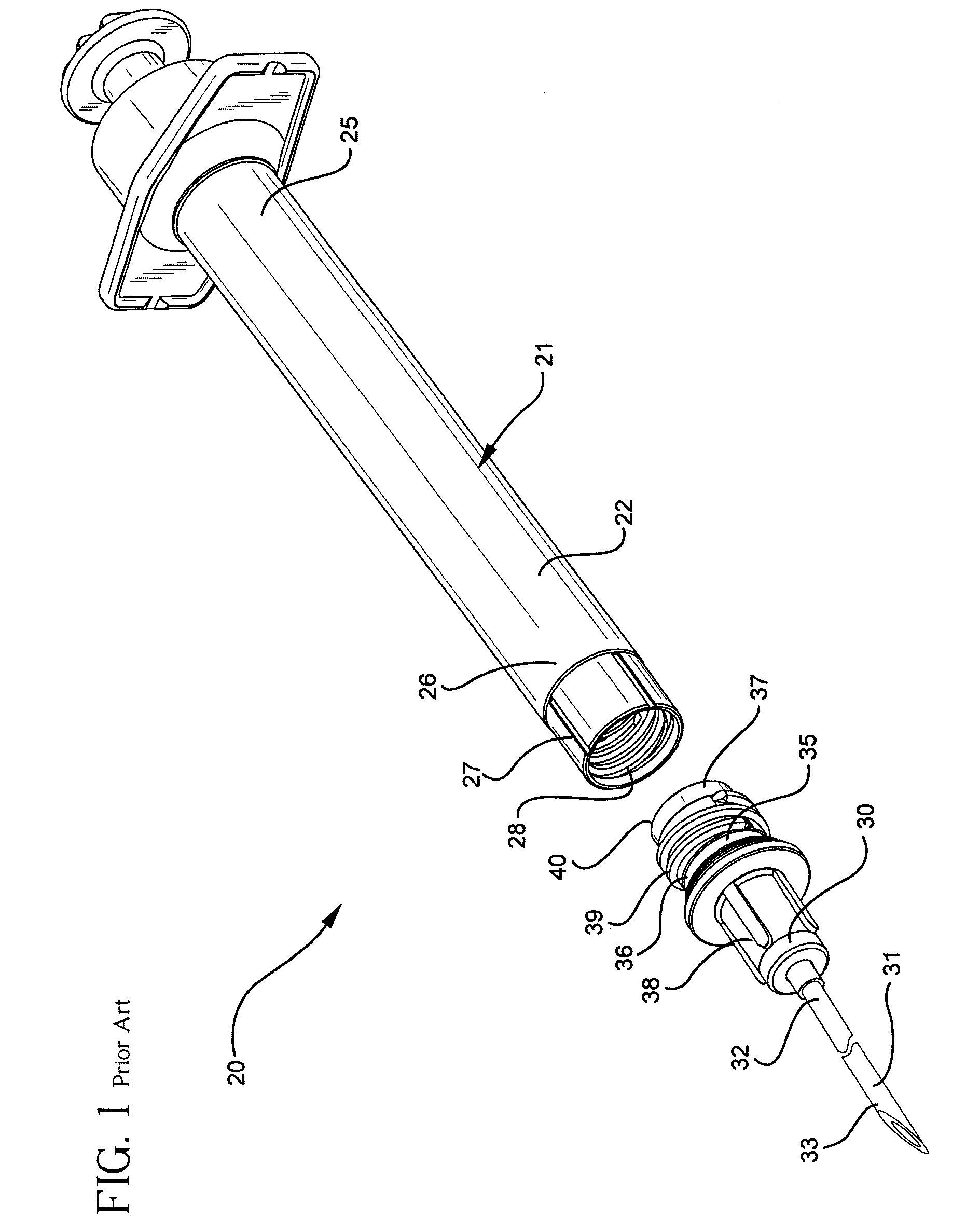
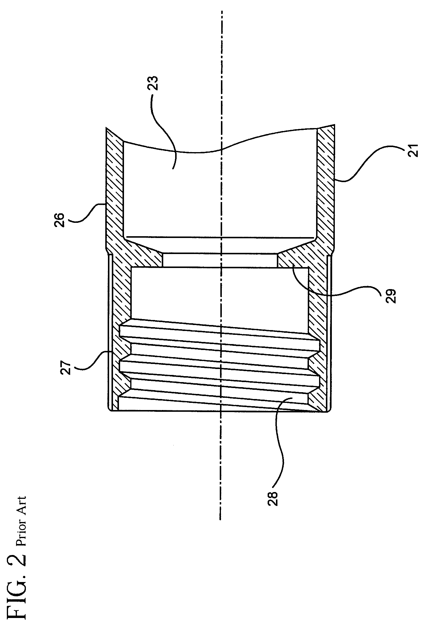
[0054]Referring to FIGS. 1-3, a prior art syringe assembly 20 includes a barrel 21 having an elongate body 22 defining a chamber 23 for retaining fluid. The barrel includes an open proximal end 25, an open distal end 26 including a collar 27 having an internal thread 28 therein. The barrel also includes an annular sealing surface 29.

[0055]A prior art needle assembly 30 includes a cannula 31 having a proximal end 32, and distal end 33 and a lumen (not shown) therethrough. A hub 35 includes a body portion 36 having a proximal...


PUM

PropertyMeasurementUnit
rotationaaaaaaaaaa
rotationaaaaaaaaaa
anglesaaaaaaaaaa

Abstract

A syringe and detachable needle assembly having binary attachment features include an elongate syringe barrel having a longitudinal axis, an open proximal end and an open distal end including a collar. The collar includes the cylindrically shaped sidewall having an inside surface and an outside surface. A needle assembly includes the hub having a body portion including a proximal end, a distal end and a conduit therethrough. A cannula having a distal end, a proximal end and a lumen therethrough is attached to the distal end of the hub so that the lumen is in fluid communication with the chamber. A lug is provided on one of the collar and the hub and a ramp and a rest surface is provided on the other of the collar and the hub. The ramp is oriented at an acute angle with respect to longitudinal axis for guiding the lug during needle assembly attachment, to the rest surface forcing the hub to contact the barrel to form a seal the hub and the barrel.

Description

FIELD OF THE INVENTION[0001]The present invention relates to syringes with removable needle assemblies. More particularly, the present invention relates to syringes having binary attachment features, and a method of making a syringe barrel for the present invention.BACKGROUND[0002]Syringe assemblies designed for use with replaceable needle assemblies usually contain a luer slip or locking luer type fitting for securing the needle assembly to the syringe barrel. These connections rely on an elongate frusto-conically shaped syringe barrel tip which frictionally engages a frusto-conically shaped passageway in a needle hub. The relatively acute angle of the syringe tip, measured from the longitudinal axis of the syringe barrel, provides an excellent seal between the syringe tip and the hub. However, slight variations in the angle or diameter of the tapered surfaces of the syringe barrel and / or the needle hub produce large variations in the relative position of the needle hub with respec...

Claims


Application Information

Patent Timeline
Patent Type & Authority Applications(United States)
IPC IPC(8): A61M5/34
CPCA61M5/3202A61M5/347B29L2031/7544B29C45/33B29C45/44A61M2005/31516
Inventor D'ARRIGO, CHRISTINA JOYSCHILLER, ERICECONOMOU, ANTHONY
Owner BECTON DICKINSON & CO
Why Eureka
Try Eureka