Vehicle and control method of vehicle

a technology of vehicle and control method, which is applied in the direction of machines/engines, instruments, gearing, etc., can solve the problems of overcharge of batteries with excess electric power, and achieve the effect of improving the fuel consumption of the vehicle and efficient operation of the internal combustion engin

Active Publication Date: 2008-04-24
TOYOTA JIDOSHA KK
View PDF13 Cites 11 Cited by
  • Summary
  • Abstract
  • Description
  • Claims
  • Application Information

AI Technical Summary

Benefits of technology

[0012] In one preferable embodiment of the vehicle of the invention, in the case of the upshift of the gear of the change speed transmission, when charging electric power for charging the accumulator does not exceed an input limit of the accumulator as a maximum chargeable electric power in the course of changing the gear of the change speed transmission to the set target speed with the operation of the internal combustion engine kept at the set target drive point, the control module controls the internal combustion engine, the rotation regulator, the motor, and the change speed transmission to actually change the gear of the change speed transmission to the set target speed without changing the drive point of the internal combustion engine but with keeping the operation of the internal combustion engine at the set target ...

Problems solved by technology

In the vehicle of the above prior art structure, however, in the case of an upshift of the gear of the transmission with the operation of the engine kept at the ...

Method used


Image

  • Vehicle and control method of vehicle
  • Vehicle and control method of vehicle
  • Vehicle and control method of vehicle

Examples


Embodiment Construction

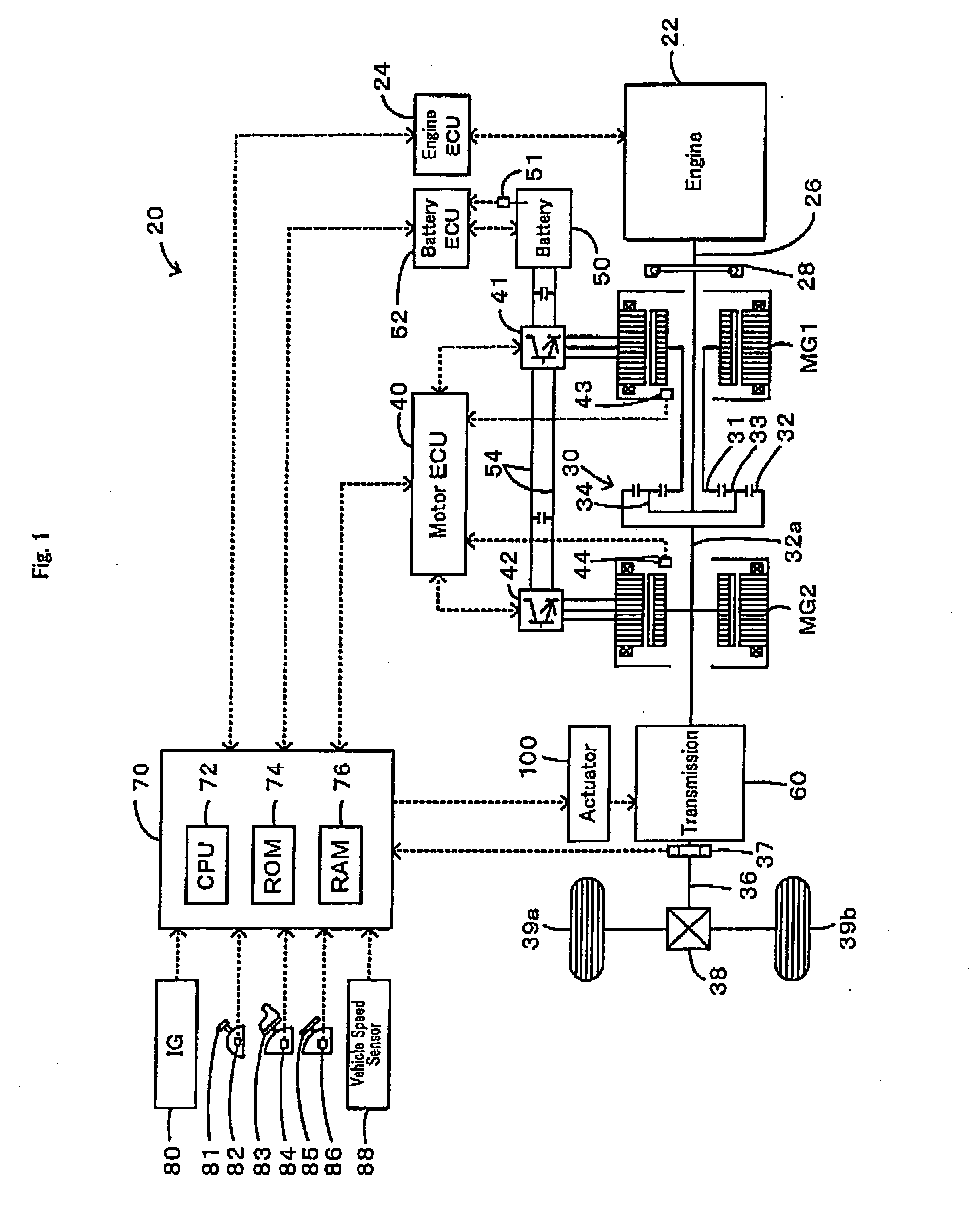
[0026] One mode of carrying out the invention is described below as a preferred embodiment with reference to the accompanied drawings. FIG. 1 schematically illustrates the configuration of a hybrid vehicle 20 in one embodiment of the invention. As illustrated, the hybrid vehicle 20 of the embodiment includes an engine 22, a three shaft-type power distribution integration mechanism 30 that is linked to a crankshaft 26 or an output shaft of the engine 22 via a damper 28, a motor MG1 that is linked to the power distribution integration mechanism 30 and has power generation capability, a motor MG2 that is linked to a ring gear shaft 32a or a power shaft connected to the power distribution integration mechanism 30, a transmission 60 that converts power of the ring gear shaft 32a and outputs the converted power to a driveshaft 36 connected to drive wheels 39a and 39b, and a hybrid electronic control unit 70 that controls the operations of the whole hybrid vehicle 20.

[0027] The engine 22 ...


PUM


Abstract

The control procedure of the invention sets a target rotation speed Ne* and a target torque Te* of an engine corresponding to a torque demand Td* required for driving the vehicle (steps S100 to S120). In response to an upshift request for a gear of a transmission, the control procedure sets a positive pre-upshift target rotation speed Nmtag to a target rotation speed Nm1* of a first motor (step S230). The control procedure changes the target rotation speed Ne* of the engine to a specific rotation speed corresponding to the pre-upshift target rotation speed Nmtag of the first motor (step S240) and subsequently implements an actual change of the gear in the transmission (step S310). This arrangement effectively restrains a battery from being overcharged with excess electric power.

Description

BACKGROUND [0001] 1. Technical Field [0002] The present invention relates to a vehicle and a control method of the vehicle. [0003] 2. Related Art [0004] One proposed structure of a vehicle is equipped with an engine, a planetary gear having a carrier connected to an output shaft of the engine, a first motor connected to a sun gear of the planetary gear, a second motor having a rotor connected to a ring gear of the planetary gear, a transmission linked to the rotor of the second motor and to a driveshaft connected with an axle of the vehicle, and a battery transmitting electric power to and from the first motor and the second motor (see, for example, Japanese Patent Laid-Open Gazette No. 2005-337491). The vehicle of this prior art structure changes the gear of the transmission while keeping the operation of the engine at an efficient drive point, thus improving the fuel consumption. SUMMARY [0005] In the vehicle of the above prior art structure, however, in the case of an upshift of ...

Claims


Application Information

Patent Timeline
IPC IPC(8): B60K1/00G06F7/00B60K6/445B60K6/448B60K6/547B60L50/16B60W10/04B60W10/06B60W10/08B60W10/10B60W10/11B60W10/115B60W10/26B60W20/00F02D29/00F02D29/02F16H61/68F16H61/684F16H61/686F16H63/40F16H63/50
CPCB60K1/02Y10S903/945B60K6/40B60K6/445B60K6/448B60K6/547B60W10/06B60W10/08B60W10/11B60W20/00B60W30/1882F16H3/66F16H3/728F16H2037/0866F16H2037/0873F16H2200/2005F16H2200/201F16H2200/2012F16H2200/2043Y02T10/6243Y02T10/6286Y02T10/6239B60K6/365B60L2240/421B60L2240/423B60L50/15Y02T10/62Y02T10/64Y02T10/7072Y02T10/70B60W20/30
Inventor MUTA, KOICHIROHIGA, MITSUAKIKITAMURA, YUICHIRO
Owner TOYOTA JIDOSHA KK
Why Eureka
Try Eureka