Bearing roller chain

a bearing roller and chain technology, applied in the direction of driving chains, mechanical equipment, transportation and packaging, etc., can solve the problems of shortened wear life of the chain, failure of the roller's rotation, and increased travel resistance of the chain, so as to prevent the leakage of lubricating oil, improve the wear resistance life of the bearing roller, and ensure the effect of rotation

a bearing roller and chain technology, applied in the direction of driving chains, mechanical equipment, transportation and packaging, etc., can solve the problems of shortened wear life of the chain, failure of the roller's rotation, and increased travel resistance of the chain, so as to prevent the leakage of lubricating oil, improve the wear resistance life of the bearing roller, and ensure the effect of rotation

US20080124015A1Inactive Publication Date: 2008-05-29FUJIWARA MAKOTO +2

Image

  • Bearing roller chain
  • Bearing roller chain
  • Bearing roller chain

Examples


Embodiment Construction

[0020]Examples of the present invention will be described. FIGS. 1 to 4 illustrate a first embodiment, an FIG. 5 is an enlarged cross-sectional view of a principal portion of a seal mechanism in a modified example of the bearing roller chain.

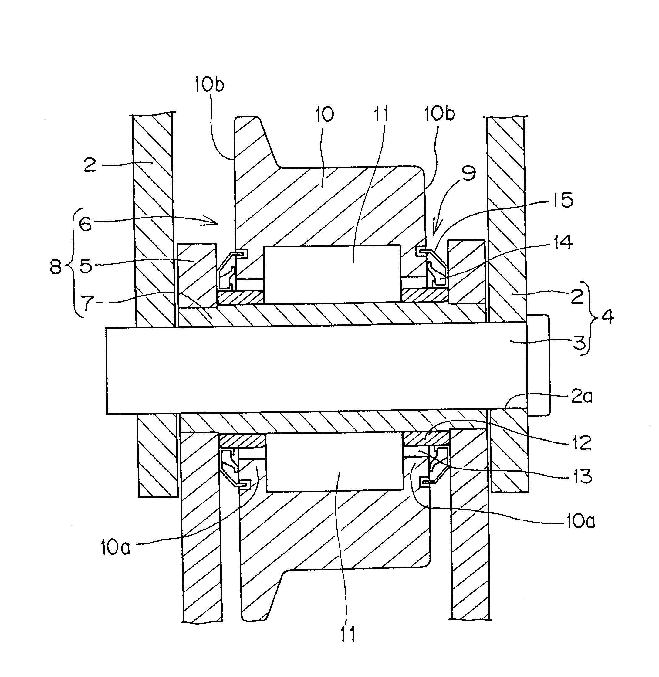
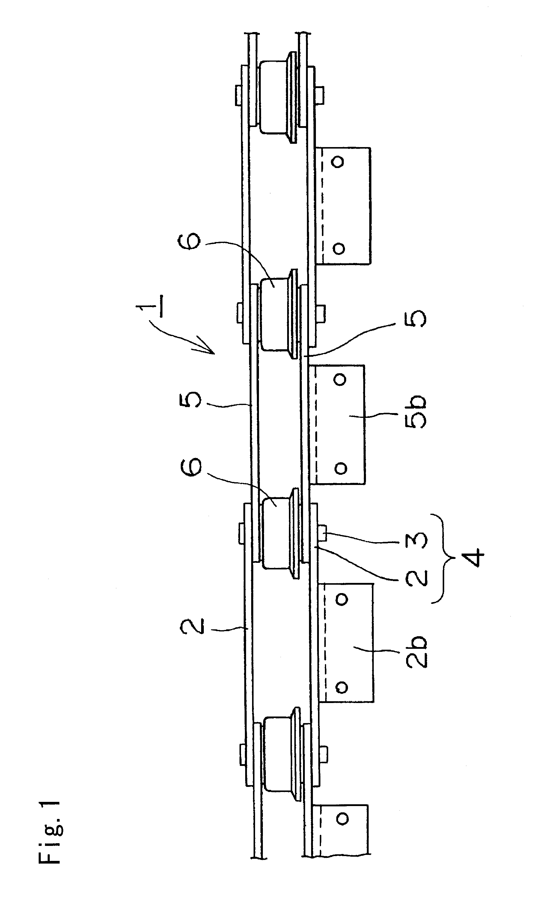
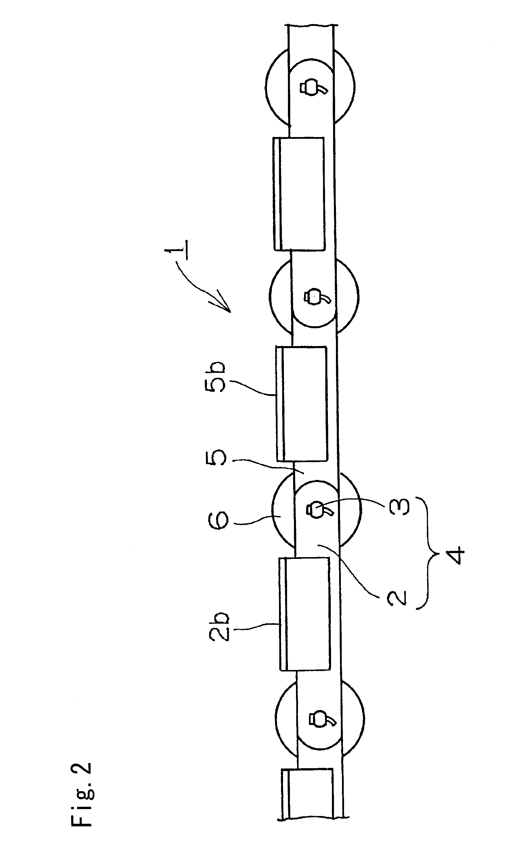
[0021]In a bearing roller chain I, as shown in FIGS. 1,2, and 3, an outer link 4 consists of a pair of outer link plates 2,2 and a connecting pin 3. Both end portions of the connecting pin 3 are fit-secured to pin holes 2a in the pair of outer link plates 2, 2. The chain includes inner links 8 (FIG. 3) in which both end portions of a bearing roller-mounted bush 7 are fit-secured to bush holes 5a of a pair of inner link plates 5, 5. The inner and outer links 8 and 4 are endlessly connected to each other by loosely fitting the connecting pins 3 into the bush 7, and as shown in FIG. 3, a seal mechanism 9 is provided between the inner link plate 5 and a bearing roller 6. It is noted that the reference numerals 2b and 5b in FIGS. 1 and 2 denote attac...


PUM


Abstract

A bearing roller chain having a seal mechanism preventing entry of foreign substance from the outside, and leaking of lubricating oil leakage to the outside and the like, thereby improving wear resistance of the bearing roller and reducing both the likelihood of rotation failure and the traveling resistance of the chain. The seal mechanism is provided between an inner link plate of the chain and the hollow bearing roller, which has a plurality of internal anti-friction rollers rotatable between the hollow bearing roller and a bush mounted between opposed inner link plates. The seal mechanism encloses the internal anti-friction rollers and comprises two parts, i.e a seal ring having an annular lip portion, which comes into close contact with an outer side surface of the bearing roller and an annular metallic seal member. The metallic seal member forms a labyrinth structure by providing a flange on an outer circumferential portion which loosely enters an annular concave groove in the outer side surface of the bearing roller. The seal mechanism provides a double sealing effect by virtue of the seal ring and the annular metallic seal member.

Description

FIELD OF INVENTION[0001]The present invention relates to a bearing roller chain used in a transmission chain, which transmits power, a conveyor chain or the like, and more specifically relates to a bearing roller chain, in which a double seal mechanism composed of a seal ring and an annular metallic seal member is provided between a hollow bearing roller and an inner link plate to prevent the entry of foreign substances such as dust, water and the like to the hollow interior of the bearing roller so that wear resistance of the bearing roller is improved.BACKGROUND OF THE INVENTION[0002]Since the bearing roller chain is adapted to high speed, high load in a case of the transmission of power, it has been widely used as a high speed transmission chain and a conveyor chain. And in the use of the bearing roller chain in an atmosphere of dust, an atmosphere of water splashing or the like, a seal mechanism is provided between an inner link plate and a bearing roller in a chain to prevent e...

Claims


Application Information

Patent Timeline
29 May 2008
Publication
US20080124015A1
IPC
F16C33/76
CPC
B65G39/09; B65G39/20; F16G13/06; F16C33/805; F16J15/164; F16C33/7889; F16J15/002; F16C19/26
Inventors
FUJIWARA, MAKOTO; TANIMURA, MAKOTO