
Bearing roller chain

a bearing roller chain and bearing roller technology, applied in the direction of driving chains, mechanical equipment, transportation and packaging, etc., can solve the problems of shortened failure of the roller's rotation, etc., to prevent any leakage of lubricating oil, improve the wear resistance life of the bearing roller, and ensure the effect of rotation

Active Publication Date: 2011-07-05
TSUBAKIMOTO CHAIN CO
View PDF21 Cites 9 Cited by
  • Summary
  • Abstract
  • Description
  • Claims
  • Application Information

AI Technical Summary

Benefits of technology

The present invention provides an improved bearing roller chain for a bearing roller that can prevent the invasion of foreign substances and leakage of lubricating oil. The seal mechanism between the inner link plates and the hollow bearing roller is sufficient to prevent such issues. The chain also has a longer wear resistant life of the bearing roller and suppresses rotation failure of the roller. The seal mechanism comprises an annular oil seal member, a spacer, and a disk-shaped seal member, which provide a multi-seal structure to prevent invasion and leakage of lubricating oil. The disk-shaped seal member has a flange that enters an annular concave groove on the roller, forming a labyrinth structure to improve seal performance. Overall, the invention solves the prior art problems of the bearing roller chain and provides an improved solution.

Problems solved by technology

Further, there is a problem that foreign substances such as dust, water or the like may enter through the gap to mix into the lubricating oil so that wear of the roller 22, the bush 23, the roller 24 and the like is promoted, resulting in failure of the roller's rotation generated by the wear, and the life of the chain is shortened.

Method used


Image

  • Bearing roller chain
  • Bearing roller chain
  • Bearing roller chain

Examples


Embodiment Construction

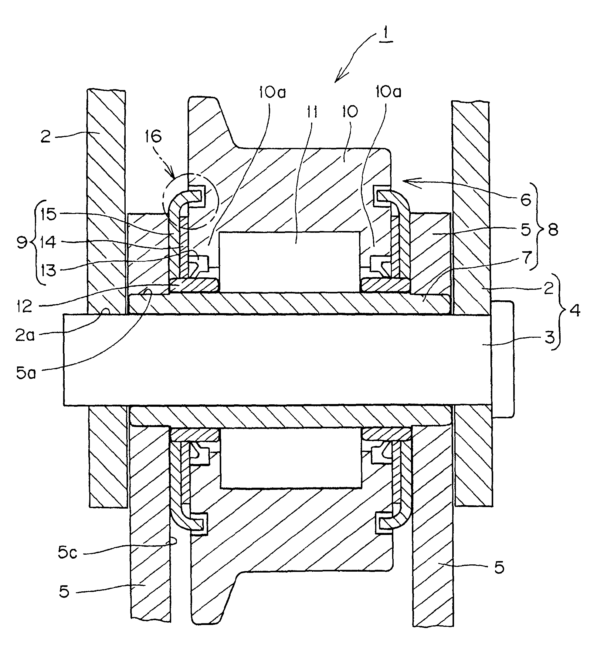
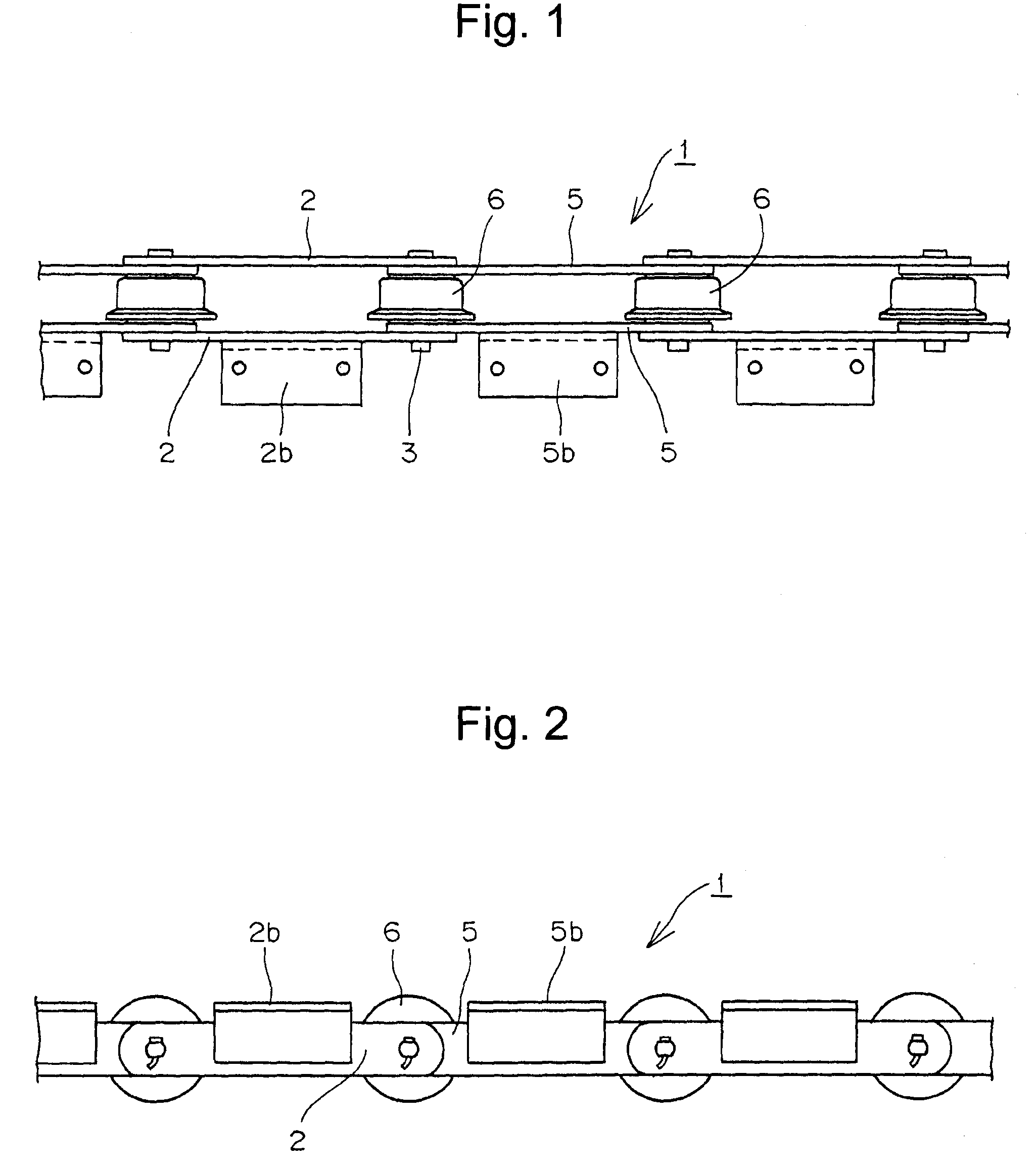
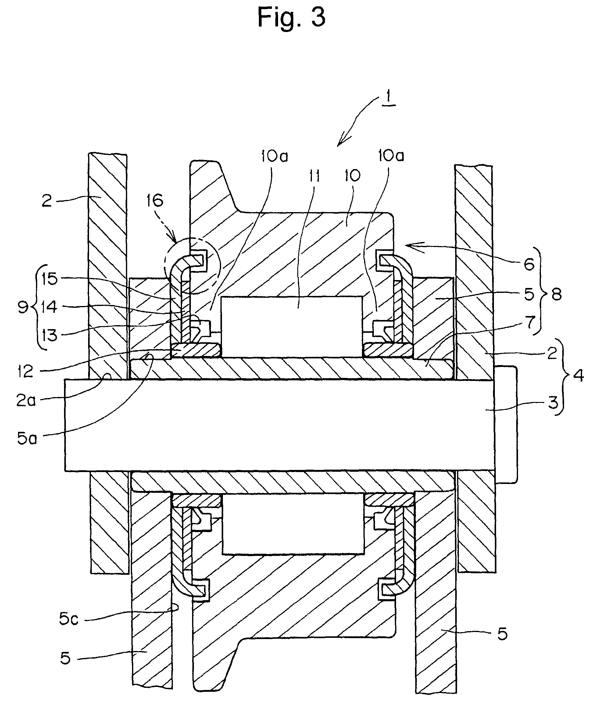
[0017]A preferred embodiment of the present invention is illustrated in FIGS. 1 to 4. A bearing roller chain 1 has outer and inner links 4 and 8 respectively.

[0018]In the bearing roller chain 1, the outer link 4 has a pair of outer link plates 2,2 with connecting pin holes 2a, in which both end portions of a connecting pin 3 are fit-secured. The inner link 8 has a pair of inner link plates 5,5 with bush holes 5a in which both end portions of a bearing roller-mounted bush 7 are fit-secured. The outer and inner links 4 and 8 are endlessly connected to each other by loosely fitting the connecting pins 3 into the bush 7, and as shown in FIG. 3, a seal mechanism 9 is provided between the inner link plate 5 and the bearing roller assembly 6. It is noted that the reference numerals 2b and 5b in FIGS. 1 and 2 denote attachments mounted between the connecting pins 3 on the outer link plate 2 and the inner link plate 5, respectively.

[0019]In the connecting pin 3, an oil passage (not shown) ma...


PUM


Abstract

A bearing roller chain which is sealed by a seal mechanism which prevents entry of foreign substances from the outside and leakage of lubricating oil leakage from the inside to the outside, resulting in an improvement in wear resistance of the bearing roller and avoidance both of rotation failure of the roller and of increased traveling resistance of the chain. A seal mechanism is provided between an inner link plate of a bearing roller chain and a bearing roller assembly carried by the link plate. The bearing roller assembly is formed by a plurality of anti-friction rollers between a hollow roller and a bush. The seal mechanism comprises an inner annular oil seal member, a spacer and a disk-shaped seal member having a flange extended toward an outer side surface of the hollow roller loosely into an outer circumferential concave groove on an end surface of the hollow roller. The disk-shaped seal member slidably comes into close contact with the inner link plate and the spacer, respectively. The flange and concave groove form a labyrinth structure protecting the inner annular seal member from entry of foreign substances from the outside. The annular seal has a plurality of lips supplementing the labyrinth seal structure.

Description

FIELD OF INVENTION[0001]The present invention relates to a bearing roller chain used in a transmission chain, which transmits power, a conveyor chain or the like, and more specifically relates to a hollow bearing roller chain, in which a multi-seal structured seal mechanism is provided between a bearing roller and an inner link plate the invasion of foreign substances such as dust, water and the like to the inside of the bearing roller can be prevented so that wear resistance life of the bearing roller is improved.BACKGROUND OF THE INVENTION[0002]Since a bearing roller chain is adapted to high speed and high load in a case of the transmission of power, it has been widely used as a high speed transmission chain and a conveyor chain. And in the use of the bearing roller chain in an atmosphere of dust, an atmosphere of water splashing or the like, a seal mechanism is provided between an inner link plate and a bearing roller in a chain to prevent invasion or entry of foreign substances ...

Claims


Application Information

Patent Timeline
Patent Type & Authority Patents(United States)
IPC IPC(8): F16G13/02
CPCF16C33/76F16C19/26F16C21/00F16C2326/58B65G17/38B65G19/20F16G13/06
Inventor FUJIWARA, MAKOTOTANIMURA, MAKOTOIMAMOTO, TETSUO
Owner TSUBAKIMOTO CHAIN CO
Learn More