Separator for immiscible liquids

a liquid separation and liquid technology, applied in the direction of filtration separation, moving filter element filter, separation process, etc., can solve the problems of expensive remediation and blockage, and achieve the effects of improving heating and silt removal, improving separation, and low friction surfa

Inactive Publication Date: 2008-06-26
SOWERBY JOHN C +2
View PDF15 Cites 19 Cited by
  • Summary
  • Abstract
  • Description
  • Claims
  • Application Information

AI Technical Summary

Benefits of technology

[0034]FIGS. 7a through 7c illustrates an improved separation device with low

Problems solved by technology

If the greases and fats solidify in the sewage system, a blockage can occur which is expensive to remediate.
Matters such as periodic cleaning of various components of the separator, such as

Method used


Image

  • Separator for immiscible liquids
  • Separator for immiscible liquids
  • Separator for immiscible liquids

Examples


Embodiment Construction

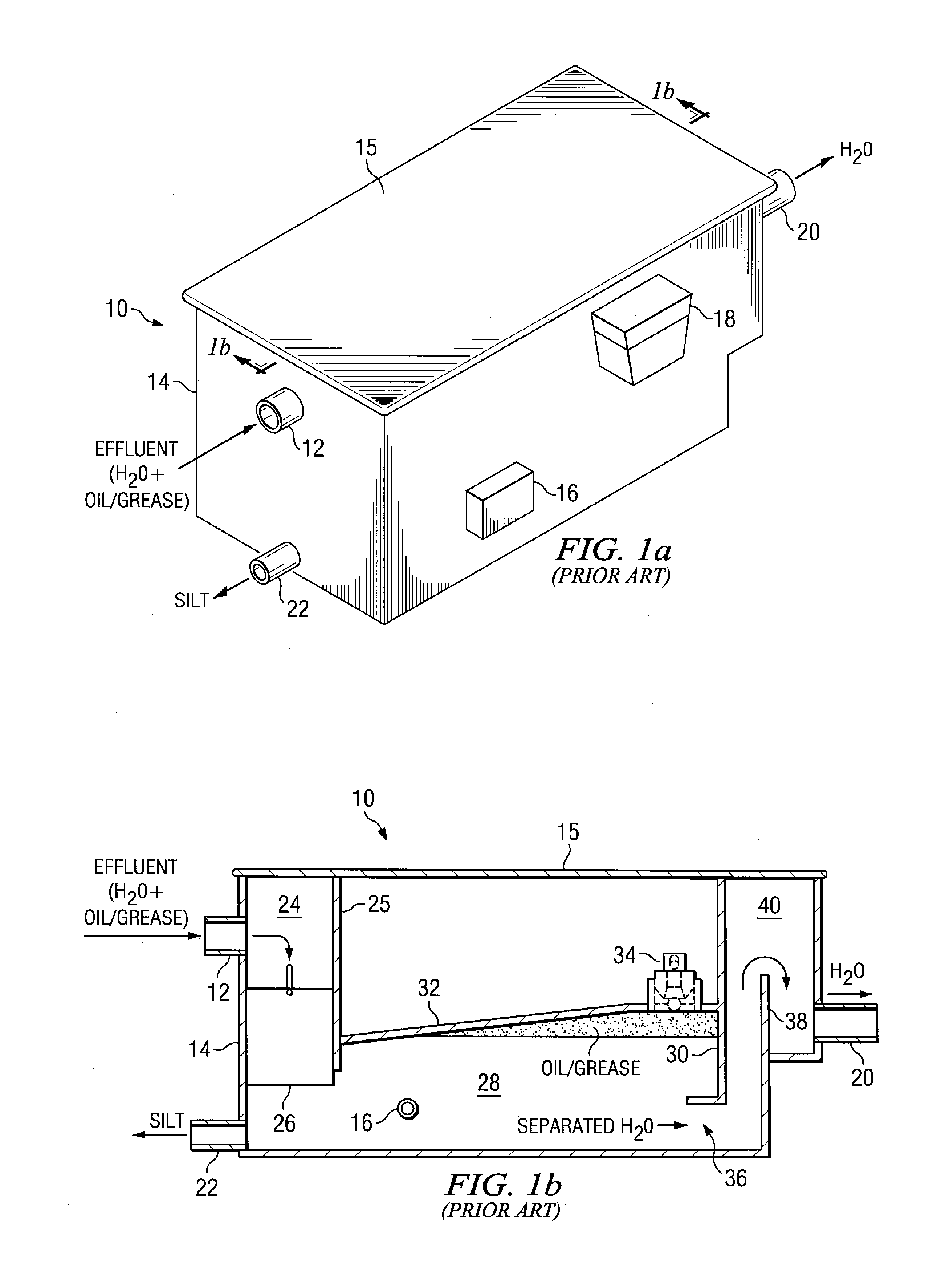
[0042]The present invention is best understood in relation to FIGS. 1-14 of the drawings, like numerals being used for like elements of the various drawings.

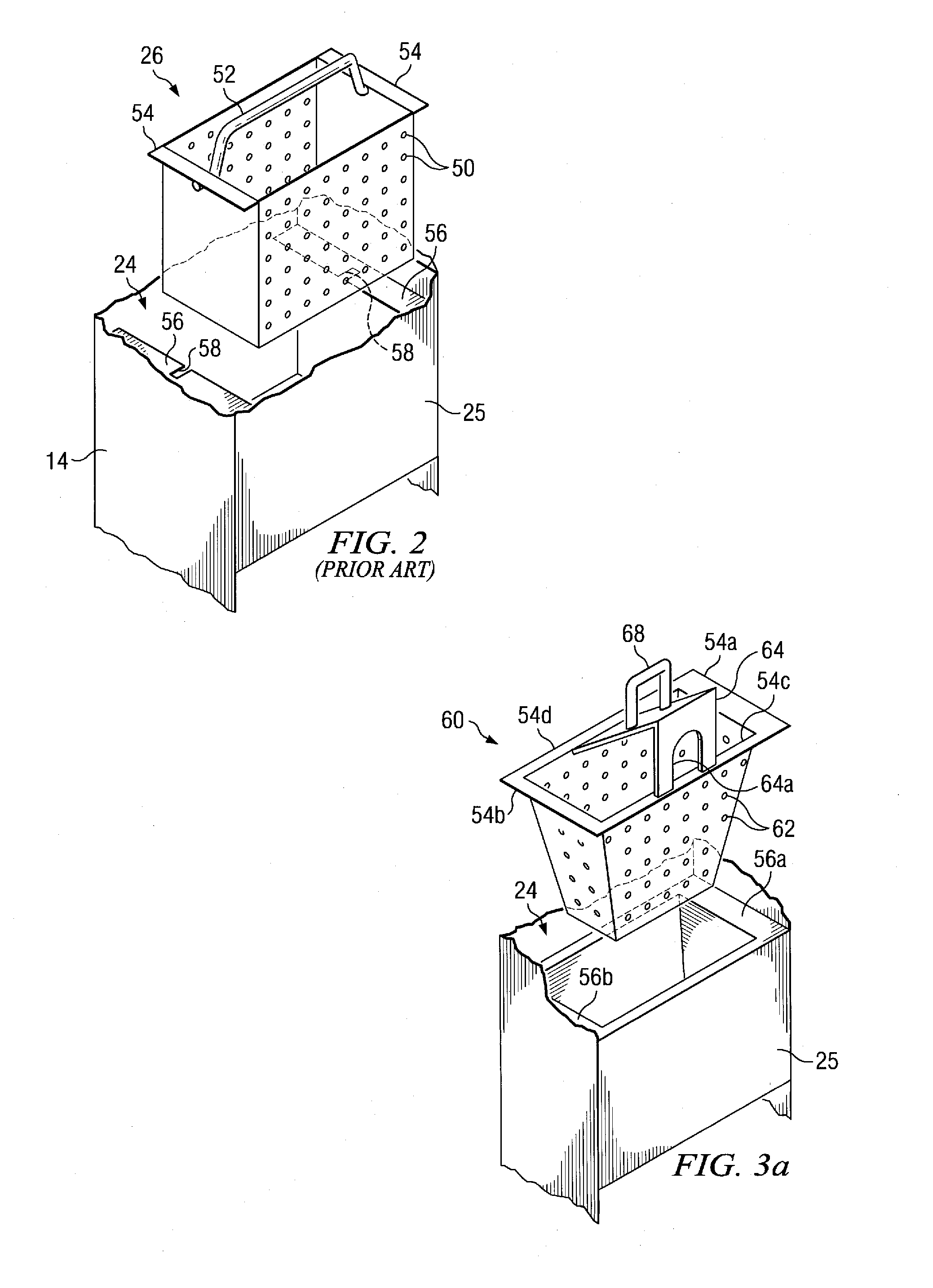
[0043]FIG. 2 illustrates a prior art filtration basket 26. The basket has a front side (facing the housing at inlet 12) and a back side (facing control plate 25) that is perforated with holes 50, as is the bottom of the basket. Since the front side is relatively flush with housing 14 and the back side is relatively flush with control plate 25, and the ends are not perforated, almost all of the effluent flow is through the holes in the bottom of the basket. Over time, food particles will accumulate on the bottom of the basket 26, severely limiting flow into the separation chamber 28.

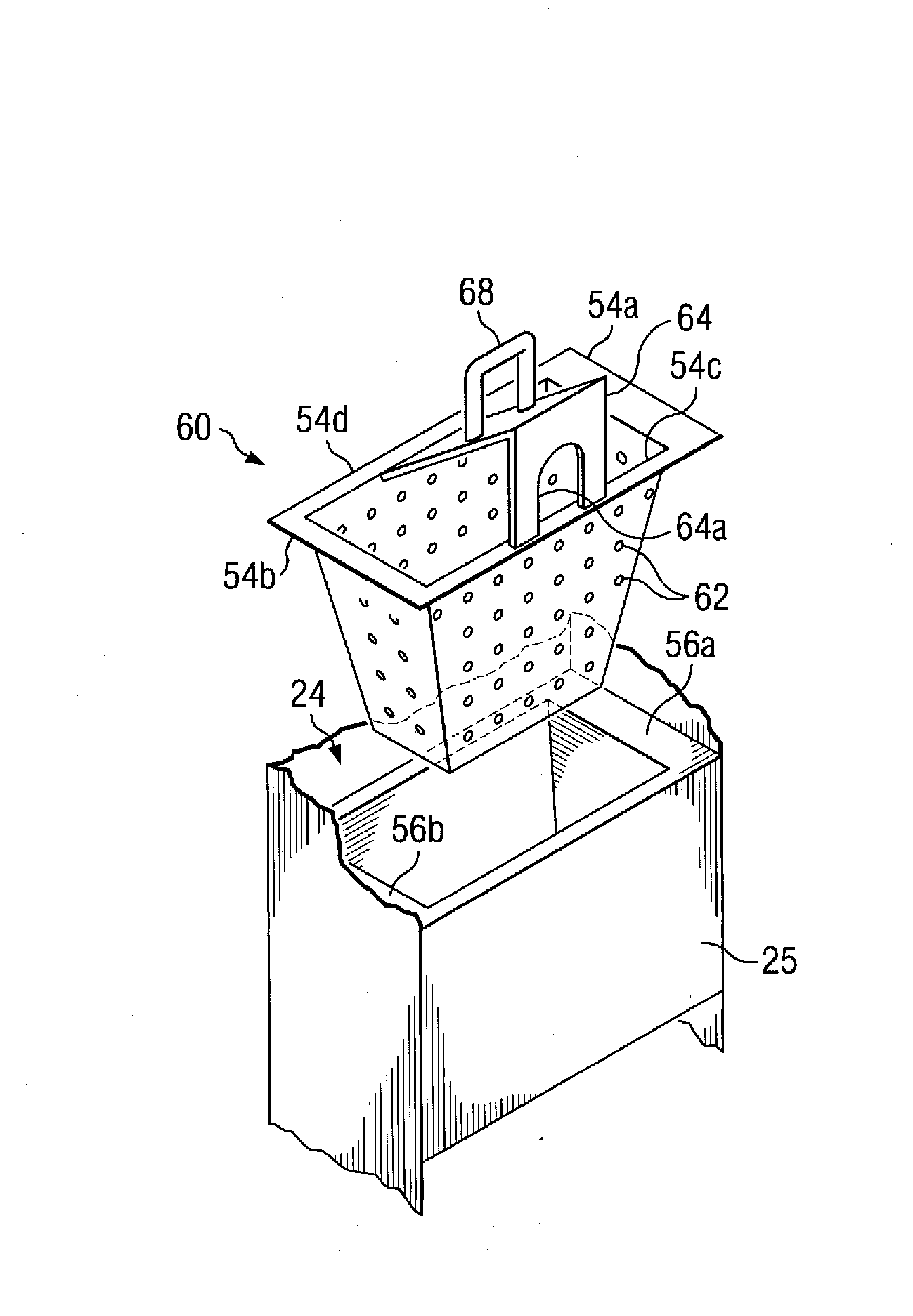
[0044]Other problems concern removal and replacement of the basket 26. The prior art uses a handle 52 which terminates through holes on either side of the basket. The basket 26 has flanges 54 on either side; flanges 54 normally rest on support clips 5...


PUM

PropertyMeasurementUnit
Lengthaaaaaaaaaa

Abstract

A separator provides improvements for better separation of an effluent into constituent parts and greater ease of use. A tapered basket provides improved flow and better filtration. A baffle directs effluent into the basket with greater force. An asymmetrical flange prevents mis-orientation the basket and baffle. An improved oil valve provides a locking mechanism to prevent dislodging of the valve during cleaning. An alternative valve uses a sensor to sense an oil/water interface and close the oil valve appropriately. A top seal prevents leakage of effluent at connection points with the lid of the housing. An underground unit allows below floor level installation of the separator. A bidirectional unit can be reversed to provide flow in either direction. A dual purpose tank can be used to store both separated oil and oil from operations for common removal.

Description

CROSS-REFERENCE TO RELATED APPLICATIONS[0001]This application is a continuation-in-part of co-pending application U.S. Ser. No. 11 / 089,069, filed Mar. 24, 2005, entitled “IMPROVED SEPARATOR FOR IMMISCIBLE LIQUIDS”, which claims the benefit of the filing date of copending provisional applications U.S. Ser. No. 60 / 556,832, filed Mar. 26, 2004, entitled “IMPROVED SEPARATOR FOR IMMISCIBLE LIQUIDS” and U.S. Ser. No. 60 / 582,993, filed Jun. 25, 2004, entitled “IMPROVED SEPARATOR FOR IMMISCIBLE LIQUIDS”.STATEMENT OF FEDERALLY SPONSORED RESEARCH OR DEVELOPMENT[0002]Not ApplicableBACKGROUND OF THE INVENTION[0003]1. Technical Field[0004]This invention relates in general to a liquid separation devices and, more particularly, to a device for separating oils and / or grease from water.[0005]2. Description of the Related Art[0006]In several industries, and in particular the food industry, there is a need to separate liquid greases, fats and oils from waste water prior to passing the water to the sew...

Claims


Application Information

Patent Timeline
IPC IPC(8): B01D24/48B01D17/00
CPCB01D17/005C02F1/40C02F2103/002B01D17/0208B01D17/0211B01D17/0214B01D17/04
Inventor SOWERBY, JOHN C.SAMUELSON, DOUGLAS F.OWEN, JONATHAN
Owner SOWERBY JOHN C
Why Eureka
Try Eureka