This helps you quickly interpret patents by identifying the three key elements:
Problems solved by technology
Method used
Benefits of technology
Benefits of technology
[0010]Embodiments of a rotary drag bit include a bit body having a face and an axis, a plurality of blades extending longitudinally and radially over the face, and at least one split cutter set. Each cutter of the split cutter set includes a cutting surface protruding at least partially from, or exposed beyond, a surface of a blade of the drag bit. All of the cutters of a split cutter set are located substantially the same radial distance from the central axis of the bit and may be located at substantially the same elevation along the central axis of the bit or at locations that enable them to substantially traverse a common cutting path upon rotation of the bit body about its central axis. A split cutter set includes a first primary cutter on a first blade and a corresponding second primary cutter on a different, second blade. One of the first and second primary cutters may be a so-called “kerfing cutter,” which largely follows the cutting path of the other primary cutter, but removes additional material from the formation into which the drag bit is drilling. A split cutter set also includes at least one backup cutter positioned rotationally or helically behind the first primary cutter or the second primary cutter so as to follow substantially the same cutting path as the primary cutter behind which it is positioned. In some embodiments, one or more backup cutters may be provided for each primary cutter of a split cutter set. Such a split cutter set enables faster drilling while reducing stress upon the cutters. In this respect, the lives of the cutters of the bit are extended and the bit is more durable than comparable conventional drag, bits, extending the life of the rotary drag bit.
Problems solved by technology
While the PDC cutting element improves drill bit efficiency in drilling many subterranean formations, the PDC cutting element is nonetheless prone to wear when exposed to certain drilling conditions, resulting in a shortened life of a rotary drag bit using such cutting elements.
The decrease in the penetration rate is a manifestation that the cutting elements of the rotary drag bit are wearing out, particularly when other drilling parameters remain constant.
While researchers continue to develop and seek out improvements for longer lasting cutters or generalized improvements to cutter performance, they fail to accommodate or implement an engineered approach to achieving longer drag bit life by maintaining or increasing ROP by taking advantage of cutting element wear rates.
Also, it is believed that conventional backup cutters in combination with their associated primary cutters may undesirably lead to balling of the blade area with formation material.
Method used
Image
Click on the blue label to locate the original text in one second.
Reading with bidirectional positioning of images and text.
Examples
first embodiment
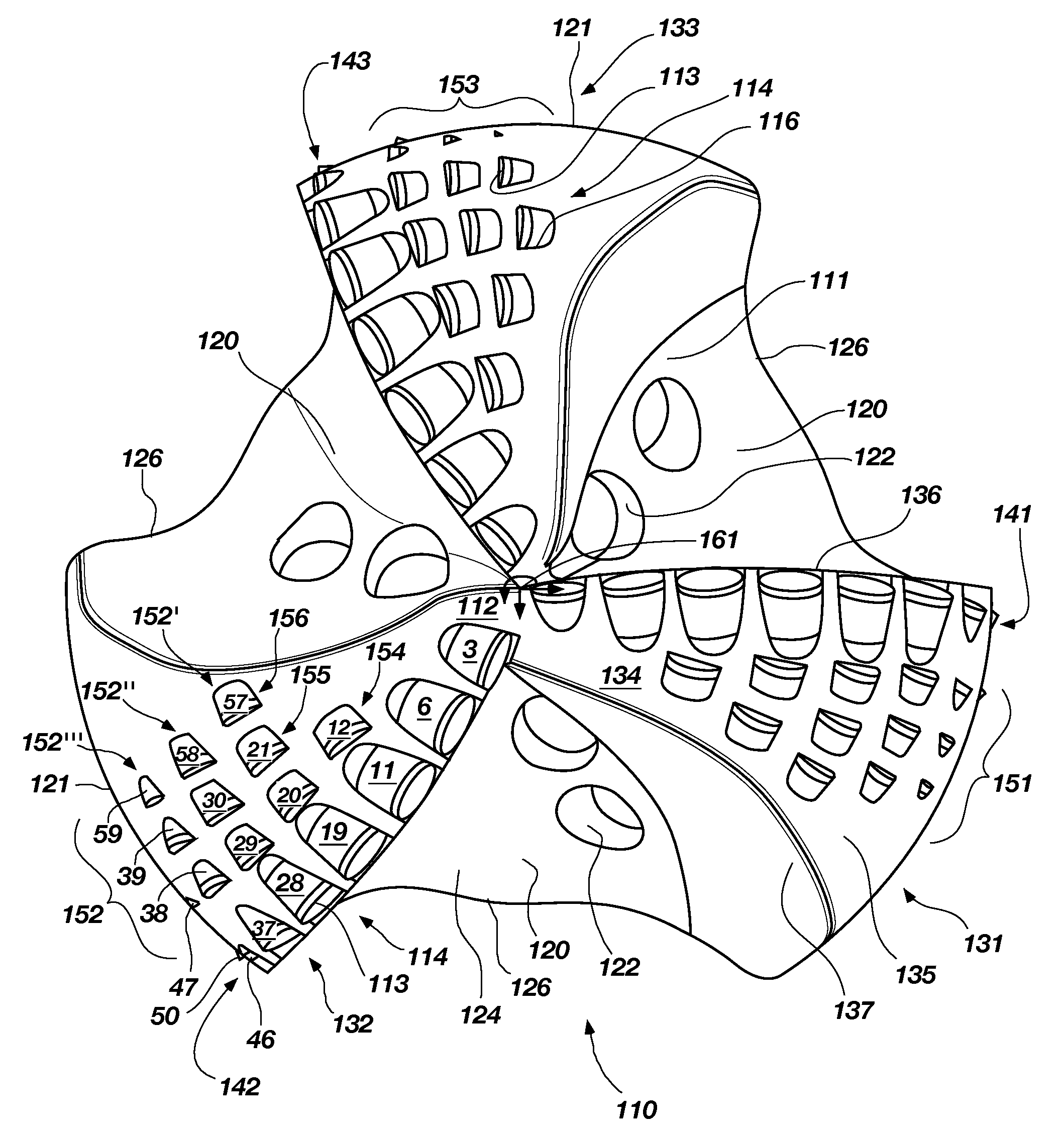
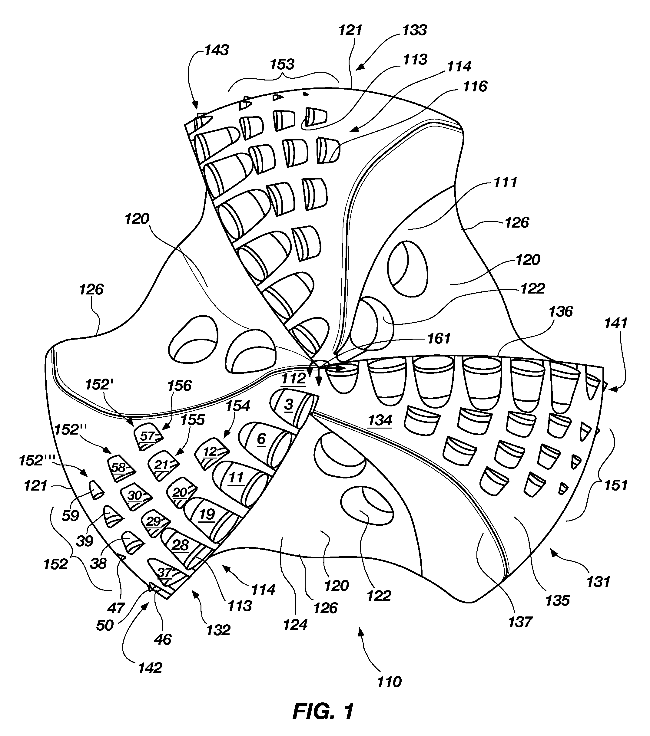
[0062]In accordance with the invention as shown in FIG. 1, the rotary drag bit 110 comprises three blades 131, 132, 133, three primary cutter rows 141, 142, 143 and three backup cutter groups 151, 152, 153, respectively. While three backup cutter groups 151, 152, 153 are included, it is contemplated that the drag bit 110 may include one backup cutter group on one of the blades or a plurality of backup cutter groups on each blade greater or less than that illustrated. Further, it is contemplated that the drag bit 110 may have more or fewer blades than the three illustrated. Each of the backup cutter groups 151, 152, 153 may have one or more backup cutter sets. For example, without limitation, the backup cutter group 152 includes three backup cutter sets 152′, 152″, 152′″. A detailed description of backup cutter sets 152′, 152″, 152′″ of the backup cutter group 152 is now provided.
[0063]Each primary cutter row 141, 142, 143 is arranged upon each blade 131, 132, 133, respectively. Rota...
second embodiment
[0079]FIG. 5 shows a frontal view of a rotary drag bit 210 in accordance with the invention. The rotary drag bit 210 comprises six blades 231, 231′, 232, 232′, 233, 233′, each having a primary or first cutter row 241 and a second cutter row 251 extending from the center line C / L of the bit 210. The cutter rows 241, 251 include cutters 214 coupled to cutter pockets 216 of the blades 231, 231′, 232, 232′, 233, 233′. It is contemplated that each blade 231, 231′, 232, 232′, 233, 233′ may have more or fewer cutter rows 241, 251 than the two that are illustrated. Also, each of the cutter rows 241, 251 may have fewer or greater numbers of cutters 214 than illustrated on each of the blades 231, 231′, 232, 232′, 233, 233′. In this embodiment, blades 231, 232, 233 are primary blades and blades 231′, 232′, 233′ are secondary blades. The secondary blades 231′, 232′, 233′ provide support for adding additional cutters 214, particularly, in the nose region 262 (see FIG. 6) where the work requireme...
fourth embodiment
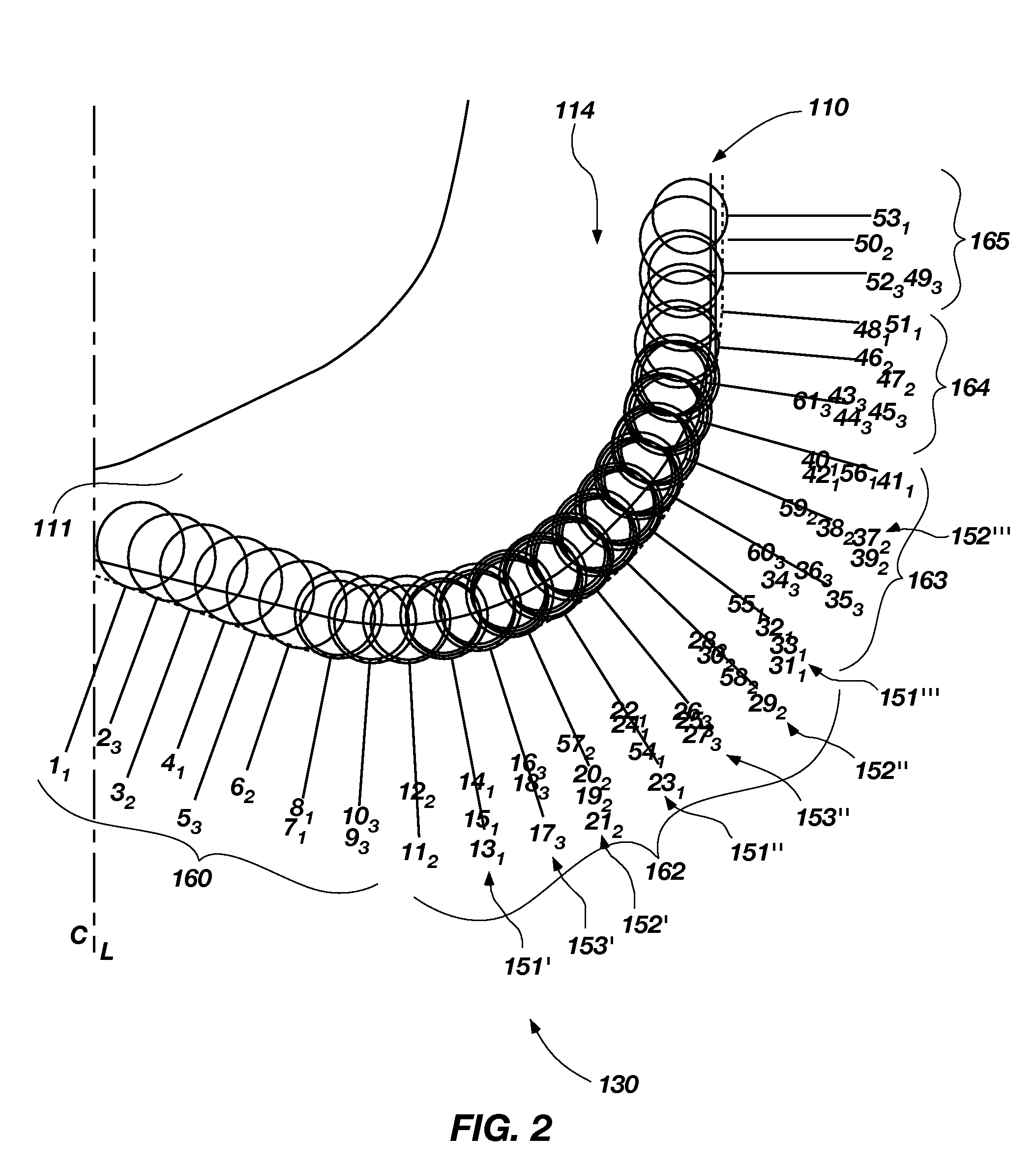
[0111]The cutters 514 in cutter rows 541, 542, 543, 544, 545, 546 are fully exposed primary cutters as shown in FIG. 23, which shows a cutter and blade profile 530 for the invention. The drag bit 510 has a cutter density of 51 cutters and a profile as represented by cutter and blade profile 530. The cutters 514 are numbered 1 through 51. The cutters 1-51, while they may include aspects of other embodiments of the invention, are not to be confused with the numbered cutters of the other embodiments of the invention. The cutters 514 in cutter rows 544, 545, 546 are positioned in adjacent rotary paths and fully exposed with respect to the cutters 514 in cutter rows 541, 542, 543 allowing the cutters 514 to provide the diamond volume in certain radial locations on the drag bit in order to optimize formation material removal while controlling cutter wear. In this respect, cutters 1-51 provide the cutter profile conventionally encountered on a 6 bladed drag bit, however the cutters 1-51 ar...
PUM
Abstract
A rotary drag bit includes a bit body having a face and an axis, a plurality of blades extending radially and longitudinally outward from the face, and at least one split cutter set. The split cutter set includes a plurality of cutters, where at least two of the cutters are primary and / or kerfing cutters located on different blades of the plurality of blades. The pair of primary and / or kerfing cutters of the split cutter set may be located substantially the same radial distance from a center line, or axis of rotation, of the bit and located at substantially the same longitude, or elevation, on the bit as one another, or follow substantially the same rotational or helicalcutting path as each other. In addition, at least one backup cutter may be located substantially the same radial distance from a center line, or axis of rotation, of the bit and located at substantially the same longitude, or elevation, on the bit as one or both primary and / or kerfing cutters, or follow substantially the same rotational or helical path as one or both of the primary and / or kerfing cutters. The cutters of a split cutter set may be configured and oriented to provide improved bit life and reduced stress on the cutters. Other embodiments of rotary drag bits are also provided, including methods therefor.
Description
CROSS-REFERENCE TO RELATED APPLICATION[0001]This application claims the benefit of U.S. Provisional Patent Application Ser. No. 60 / 897,457, filed Jan. 25, 2007, for “ROTARY DRAG BIT,” the entire disclosure of which is hereby incorporated herein by this reference.TECHNICAL FIELD[0002]The present invention, in several embodiments, relates generally to a rotary drag bit for drilling subterranean formations and, more particularly, to rotary drag bits having select plural kerfing cutter configurations configured to enhance cutter life and performance, including methods therefor.BACKGROUND[0003]Rotary drag bits have been use for subterranean drilling for many decades, and various sizes, shapes and patterns of natural and synthetic diamonds have been used on drag bit crowns as cutting elements. A drag bit can provide an improved rate of penetration (ROP) over a tri-cone bit in many formations.[0004]Over the past few decades, rotary drag bit performance has been improved with the use of a p...
Claims
Application Information
Patent Timeline
Application Date:The date an application was filed.
Publication Date:The date a patent or application was officially published.
First Publication Date:The earliest publication date of a patent with the same application number.
Issue Date:Publication date of the patent grant document.
PCT Entry Date:The Entry date of PCT National Phase.
Estimated Expiry Date:The statutory expiry date of a patent right according to the Patent Law, and it is the longest term of protection that the patent right can achieve without the termination of the patent right due to other reasons(Term extension factor has been taken into account ).
Invalid Date:Actual expiry date is based on effective date or publication date of legal transaction data of invalid patent.

