Liquid crystal displaying device

a liquid crystal display and display device technology, applied in non-linear optics, instruments, optics, etc., can solve the problem of not bringing about sufficient reflective contrast, and achieve the effect of reducing coloring, bulk thinner, and high contrast ratio

Active Publication Date: 2008-08-21
PANASONIC LIQUID CRYSTAL DISPLAY CO LTD +1
View PDF6 Cites 6 Cited by
  • Summary
  • Abstract
  • Description
  • Claims
  • Application Information

AI Technical Summary

Benefits of technology

[0018]The transflective liquid crystal display device of each foregoing display system is arranged to reduce the coloring when displa...

Problems solved by technology

Disadvantageously, these prior art documents do not disclose a way of building the retardar plate in a...

Method used


Image

  • Liquid crystal displaying device
  • Liquid crystal displaying device
  • Liquid crystal displaying device

Examples


first embodiment

[0041]The first embodiment will be described with reference to the appended drawings.

[0042]The first embodiment concerns with the transflective liquid crystal display (simply referred to as the transflective LCD) device of the ECB system. The ECB system transflective LCD device is arranged so that when applying no voltage the liquid crystal molecules are aligned horizontally with respect to the substrate but when applying a certain voltage the liquid crystal the liquid crystal molecules are rotated vertically with respect to the substrate. This ECB system transflective LCD uses an optical compensation film and includes a retardar plate built in a liquid crystal cell (simply referred to as an in-cell retardar as described above). In this embodiment, the in-cell retardar is used for arranging the transflective LCD, so that the ECB system transflective LCD of this embodiment may be made thinner in bulk than the conventional LCD.

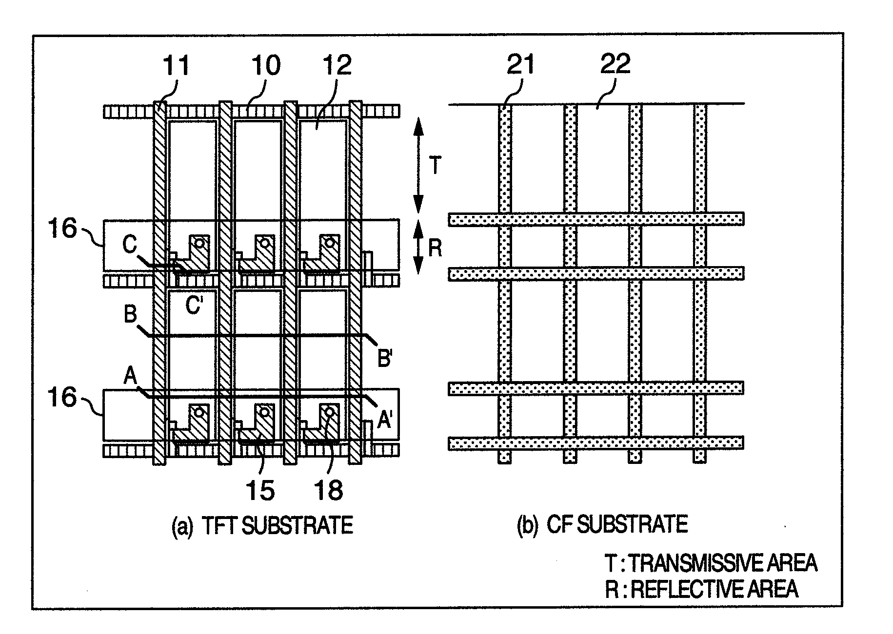
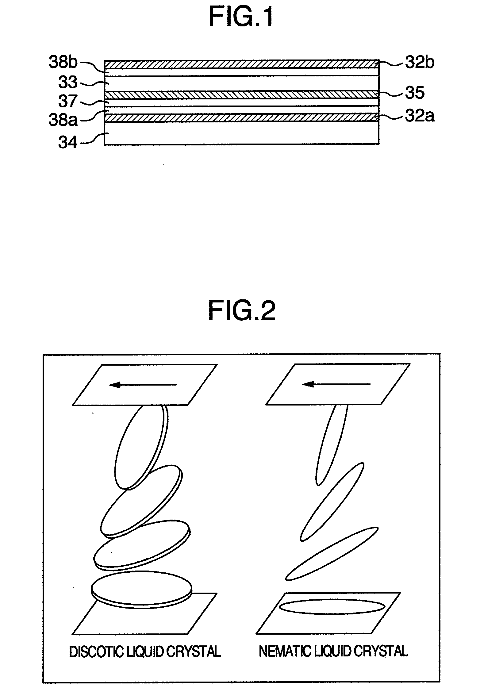
[0043]FIG. 1 shows a schematic section of the LCD device a...

second embodiment

[0082]In turn, the description will be oriented to the LCD device according to another embodiment.

[0083]The second embodiment concerns with the transflective ECB-LCD device that uses the in-cell retardar and thus is not required to have the outside retardar, in which device as to the phase difference values of the retardar built in the reflective portion, the values of the blue and the green are equal to each other but the value of the red is different therefrom or the values of the blue, the green and the red are different from one another. Further, the phase difference values of the retarders built in the color pixels do not have the relation of λ / 4. The second embodiment makes it possible to improve the reflected color when displaying a black image and to improve the reflective contrast ratio.

[0084]The sectional structure of the LCD device according to the second embodiment is the same as that shown in FIG. 8. The schematic sectional structure of the transmissive portion is the s...

third embodiment

[0093]In turn, the description will be oriented to the LCD device according to another embodiment of the present invention.

[0094]This embodiment is arranged to control the phase difference value of the in-cell retardar based on not the birefringence but the thickness. This embodiment arranged to execute the thickness-based control offers the same effect as the second embodiment.

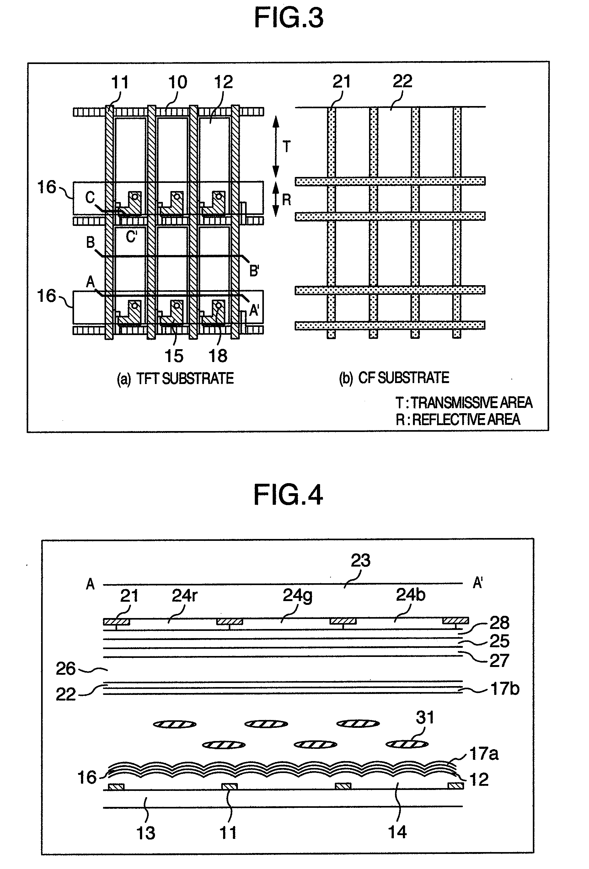
[0095]The different respect between this third embodiment and the second embodiment will be described below with reference to FIG. 14. FIG. 14 is a section showing the second substrate 23 to be used for the third embodiment. Since FIG. 14 is an explanatory view of the form of the in-cell retardar 25, the color filter 24 and the like are not shown therein. The step 40 used for the in-cell retardar is located on the second substrate 23 so as to properly adjust the thickness of the in-cell retardar 25.

[0096]It is preferable that the step 40 is formed by an organic insulating film, for example. To form the step, ...


PUM


Abstract

A transflective liquid crystal display device is arranged to make the overall structure thinner and enhance a reflecting contrast ratio. The transflective liquid crystal display includes a first substrate, a second substrate, a liquid crystal layer laid between the substrates, a first polarization plate located on the opposite side of the first substrate to the side where the liquid crystal layer is located, a second polarization plate located on the opposite side of the second substrate to the side where the liquid crystal layer is located, and a plurality of pixels formed between the substrates, each of the pixels having a reflective area and a transmissive area. An in-cell retardar is located between the second substrate and the liquid crystal layer. An optical compensation film is located between the first substrate and the first polarization plate, between the second substrate and the second polarization plate, or both.

Description

BACKGROUND OF THE INVENTION[0001]1. Field of the Invention[0002]The present invention relates to a liquid crystal display device, and more particularly to a transflective liquid crystal display device.[0003]2. Description of the Related Art[0004]Today, a transflective liquid crystal display device provided with both reflective and transflective display capabilities is now being developed. The transflective liquid crystal display device is arranged to reduce the power consumption in a bright environment by turning off its backlight unit and to allow a user to view an image on the screen in a gloomy or dark environment by turning on the backlight unit. It means that the transflective liquid crystal display is fitted to portable instruments such as a portable phone and a digital camera to be used in many kinds of illuminating environments.[0005]The transflective liquid crystal display device is required so that a transmissive area and a reflective area are individually located in each ...

Claims


Application Information

Patent Timeline
IPC IPC(8): G02F1/13363G02F1/1335
CPCG02F1/1395G02F1/133555
Inventor OKA, SHINICHIROITOU, OSAMUHIROTA, SHOICHI
Owner PANASONIC LIQUID CRYSTAL DISPLAY CO LTD
Why Eureka
Try Eureka