Light source control apparatus and method for controlling light source

a control apparatus and light source technology, applied in the field of control apparatus and methods, can solve the problems of degrading the image quality of lcds, degrading the image quality of images, and degrading image quality of images, and achieve the effect of reducing the manufacturing cos

Inactive Publication Date: 2008-09-18
NOVATEK MICROELECTRONICS CORP
View PDF8 Cites 6 Cited by
  • Summary
  • Abstract
  • Description
  • Claims
  • Application Information

AI Technical Summary

Benefits of technology

[0011]The present invention is directed to providing a light source control apparatus, capable of compensating a brightness of a single LED or a plurality of LEDs connected in series, such that an image quality of the LCDs is stabilized and a stringent quality control is not required in mass production of LCDs, thereby reducing the manufacturing cost.

Problems solved by technology

However, this control method may degrade the quality of images, as shown in FIG. 1.
However, the temperature coefficients and degrees of aging of the LEDs are not completely identical, so that the light-emitting situation of each LED varies, and the circuit architecture of the conventional control apparatus can not adjust the LED individually, thus degrading the image quality of LCDs.
Moreover, as the conventional architecture can only amend the brightness of the LEDs 101-10N at the same time, and the brightness compensation can not be performed on an individual LED, the image quality is degraded.
Therefore, a strict quality control is necessary for mass production, and the manufacturing cost remains high, and the quality is still difficult to control.

Method used


Image

  • Light source control apparatus and method for controlling light source
  • Light source control apparatus and method for controlling light source
  • Light source control apparatus and method for controlling light source

Examples


Embodiment Construction

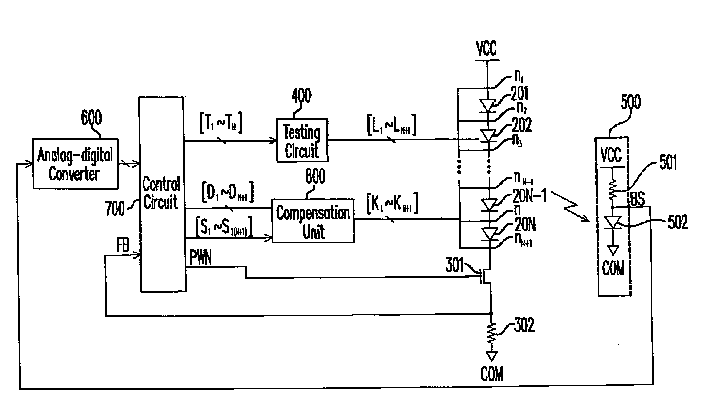
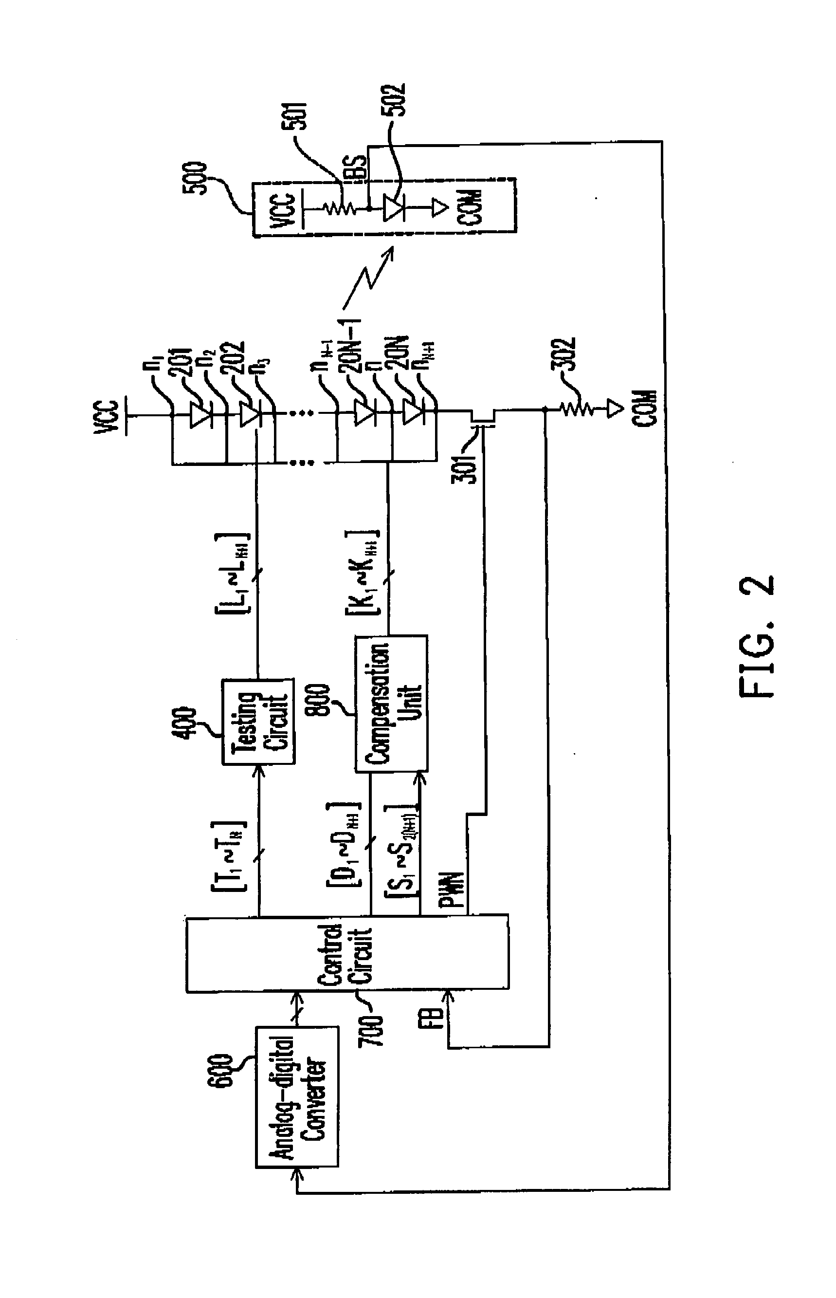
[0039]FIG. 2 is a circuit diagram of a light source control apparatus according to an embodiment of the present invention. The light source control apparatus is used to control the light-emitting brightness of the light-emitting devices 201-20N. In this embodiment, the above light-emitting devices are all implemented by LEDs which are coupled in the way as shown in FIG. 2, and the details will not be described. N+1 nodes are sequentially defined at two terminals of each light-emitting device, and are indicated by n1-nN+1, where, N is a natural number.

[0040]The above light source control apparatus includes a testing circuit 400 and a compensation circuit, and further includes a MOS transistor 301 and an impedor 302 (the operations of the MOS transistor 301 and the impedor 302 will be illustrated hereinafter). The testing circuit 400 is sequentially coupled to the nodes n1-nN+1 through the connection lines L1-LN+1 to transmit a testing current to light-emitting devices between Ith nod...


PUM


Abstract

A light source control apparatus and a method for controlling light source are provided. The light source control apparatus is used to controlling N light-emitting devices connected in series. N+1 nodes are sequentially defined at two terminals of each light-emitting device mentioned above, where N is a natural number. The light source control apparatus includes a testing circuit and a compensation circuit. The testing circuit is coupled to the nodes to transmit a testing current to light-emitting devices between Ith node and Jth node, where I and J are natural numbers, and N+1>=J>I>=1. The compensation circuit is coupled to the nodes to measure a brightness of light-emitting devices between Ith node and Jth node, decide a value of a compensation current according to an intensity of the brightness, and provide the compensation current to light-emitting devices between Ith node and Jth node.

Description

CROSS-REFERENCE TO RELATED APPLICATION[0001]This application claims the priority benefit of Taiwan application serial no. 96109060, filed Mar. 16, 2007. All disclosure of the Taiwan application is incorporated herein by reference.BACKGROUND OF THE INVENTION[0002]1. Field of the Invention[0003]The present invention relates to a control apparatus and method. More particularly, the present invention relates to a light source control apparatus and a method for controlling a light source.[0004]2. Description of Related Art[0005]RGB light emitting diodes (LEDs) can exhibit a wider color gamut as compared with cold cathode fluorescent lamps (CCFLs), wherein R, G, B are red, green, and blue signals of three primary colors. Therefore, LED has a more diversified color performance than the CCFL, and has been widely used as light-emitting sources of liquid crystal displays (LCD).[0006]However, since the size of the LCDs is increasingly enlarged, and the number of the LEDs used in an LCD of a la...

Claims


Application Information

Patent Timeline
Patent Type & Authority Applications(United States)
IPC IPC(8): G09G3/32
CPCG09G3/3406G09G2320/0233G09G2320/064H05B33/089G09G2360/145H05B33/083H05B33/0869G09G2320/0693H05B45/22H05B45/48H05B45/54
Inventor HUANG, CHUN-YI
Owner NOVATEK MICROELECTRONICS CORP
Why Eureka
Try Eureka