
Multimedia module in switch case
- Summary
- Abstract
- Description
- Claims
- Application Information
AI Technical Summary
Benefits of technology
Problems solved by technology
Method used
Image

Examples
Embodiment Construction
[0011]The following description of the preferred embodiment is provided to understand the features and the structures of the present invention.
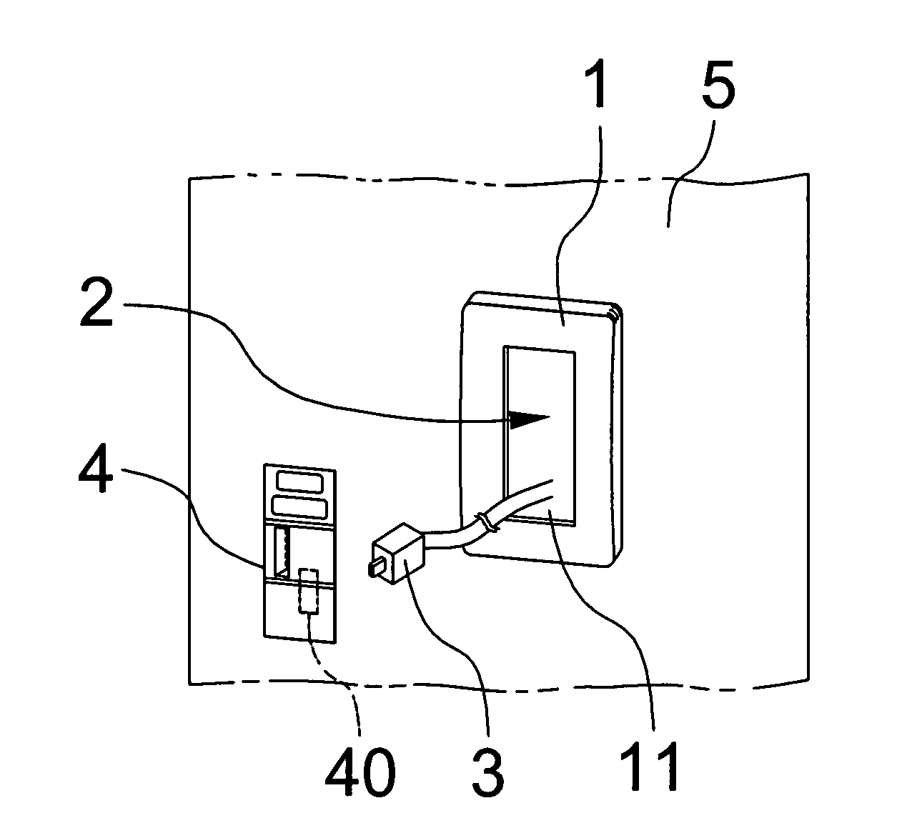
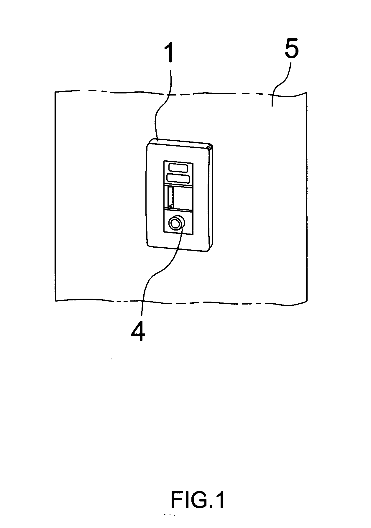
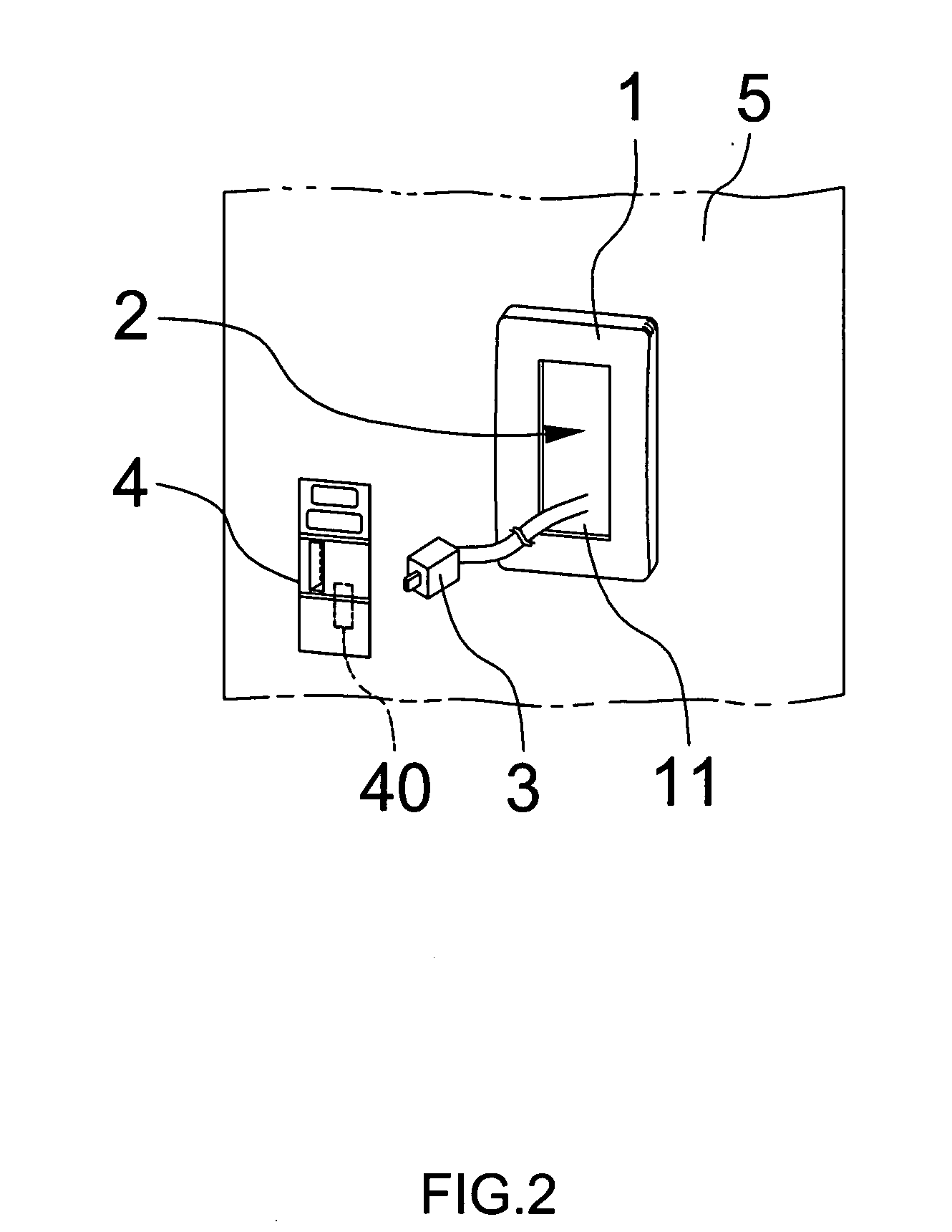
[0012]Please refer to FIG. 1 to FIG. 3, which are a perspective view, an explosive view and a block view showing a preferred embodiment according to the present invention. As shown in the figures, the present invention is a multimedia module in a switch case, comprising a panel 1, a power source 2, a transformer 3 and an electronic device 4, where the electronic device 4 comprising one electronic component or a plurality of electronic components is set in the panel 1 of a switch case to obtain variety and flexibility.
[0013]The panel 1 is set at a proper place on a wall surface 5; and the panel 1 has at least one hole 11.
[0014]The power source 2 provides an alternating current having a voltage between 110 volts and 220 volts; and the power source 2 is set between the panel 1 and the wall surface 5.
[0015]The transformer 3 is connected with the ...
PUM
 Abstract
Description
Claims
Application Information