UV curable ink-jet recording apparatus

a recording apparatus and inkjet technology, applied in the field of inkjet recording apparatus, can solve the problems of nozzle blockage or failure, image quality reduction, and other problems, and achieve the effects of reducing ink curing, high productivity, and stably using

Inactive Publication Date: 2008-10-02
FUJIFILM CORP
View PDF6 Cites 15 Cited by
  • Summary
  • Abstract
  • Description
  • Claims
  • Application Information

AI Technical Summary

Benefits of technology

[0018]According to the configuration, it is possible to obtain an ink-jet recording apparatus in which also both leakage light and reflected light are trapped by simple means to completely suppress ink curing, and which has a high productivity, can perform printing on various recording media, is compact, and can be stably used.

Problems solved by technology

On the other hand, in an apparatus having a high productivity, when a web-like recording medium is transported at a high speed, transport wobbling of a base member occurs, and the image quality is reduced.
In this case, there is a possibility that a UV ray which is emitted from the light source, or that which is emitted from the light source and reflected from the surface of the recording medium enters a nozzle face, and inks on the nozzle face and in the vicinities of ejection ports react with UV light to be thickened or cured, thereby causing nozzle clogging or an ejection failure.

Method used


Image

  • UV curable ink-jet recording apparatus
  • UV curable ink-jet recording apparatus
  • UV curable ink-jet recording apparatus

Examples


embodiment 1

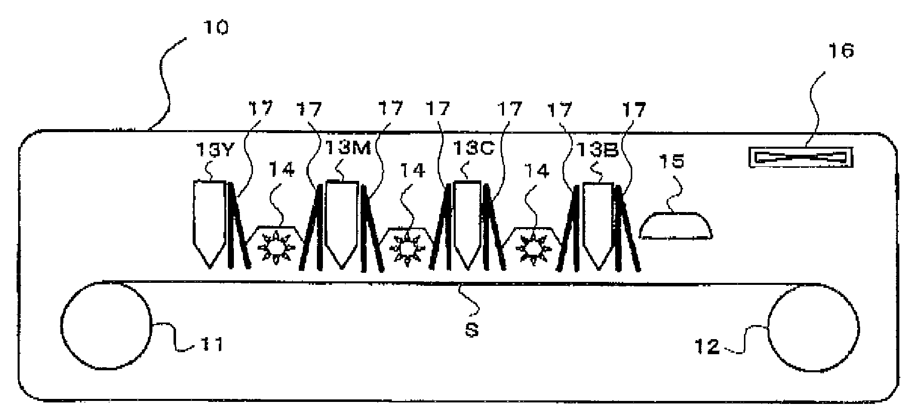
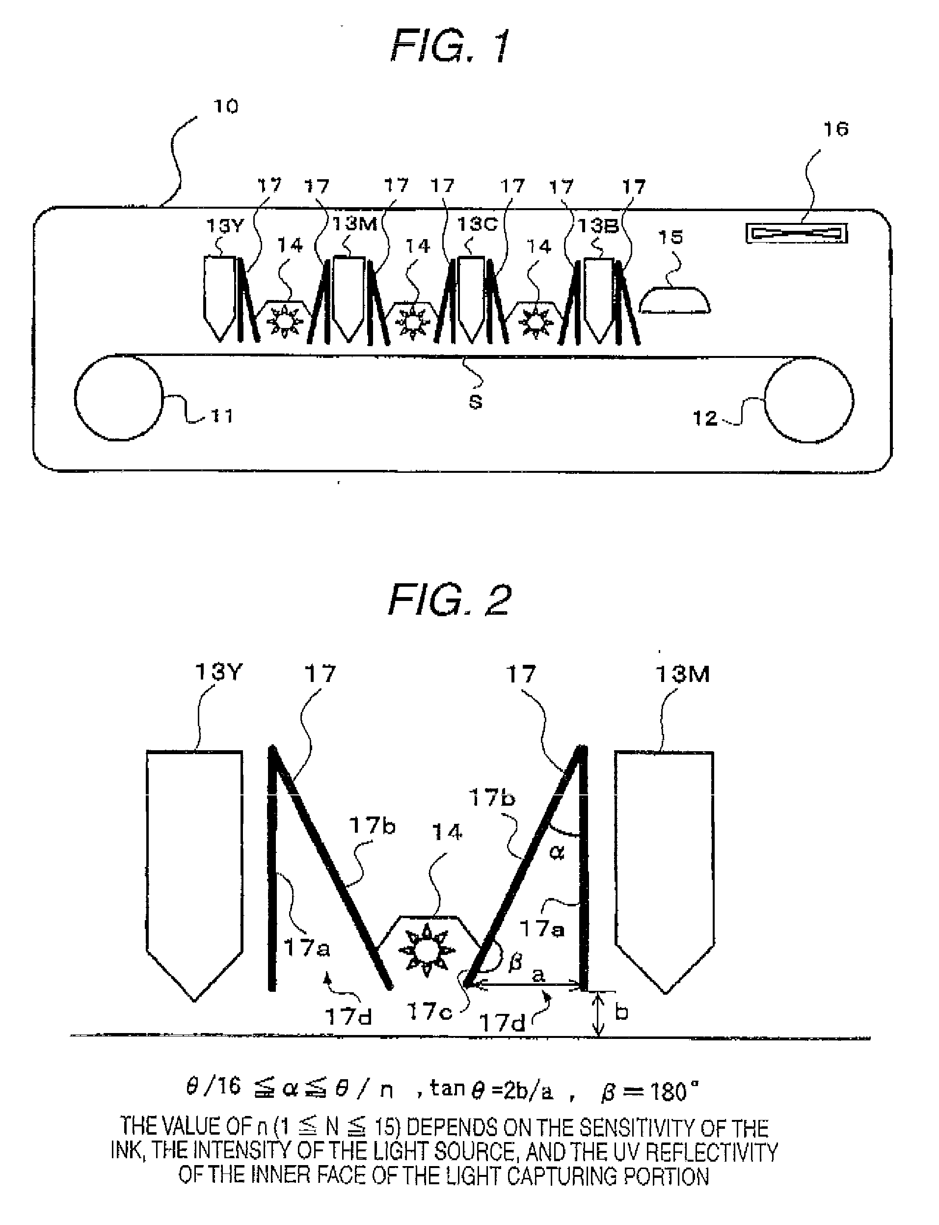
[0047]FIG. 1 is a diagram of a UV curable ink-jet recording apparatus of Embodiment 1 of the invention. In FIG. 1, 10 denotes a single-pass ink-jet apparatus.

[0048]In the single-pass ink-jet apparatus 10, the recording medium S is taken out from a recording medium roll 11 which is wound in a roll. First, during when the recording medium S is transported under a full-line ink-jet head 13Y for Y (yellow) color in which many ink-jet nozzles are arranged in the width direction of the recording medium S, a Y-color ink is ejected onto the recording medium S so as to form a desired image. Immediately after the ejection, the recording medium S is passed under a UV irradiation lamp 14. During the passage, the Y-color ink which is a UV curable ink, and which is ejected onto the recording medium S is exposed to UV light to be subjected to semi-curing.

[0049]Next, during when the recording medium S is transported under a full-line ink-jet head 13M for M (magenta) color in which many ink-jet nozz...

embodiment 2

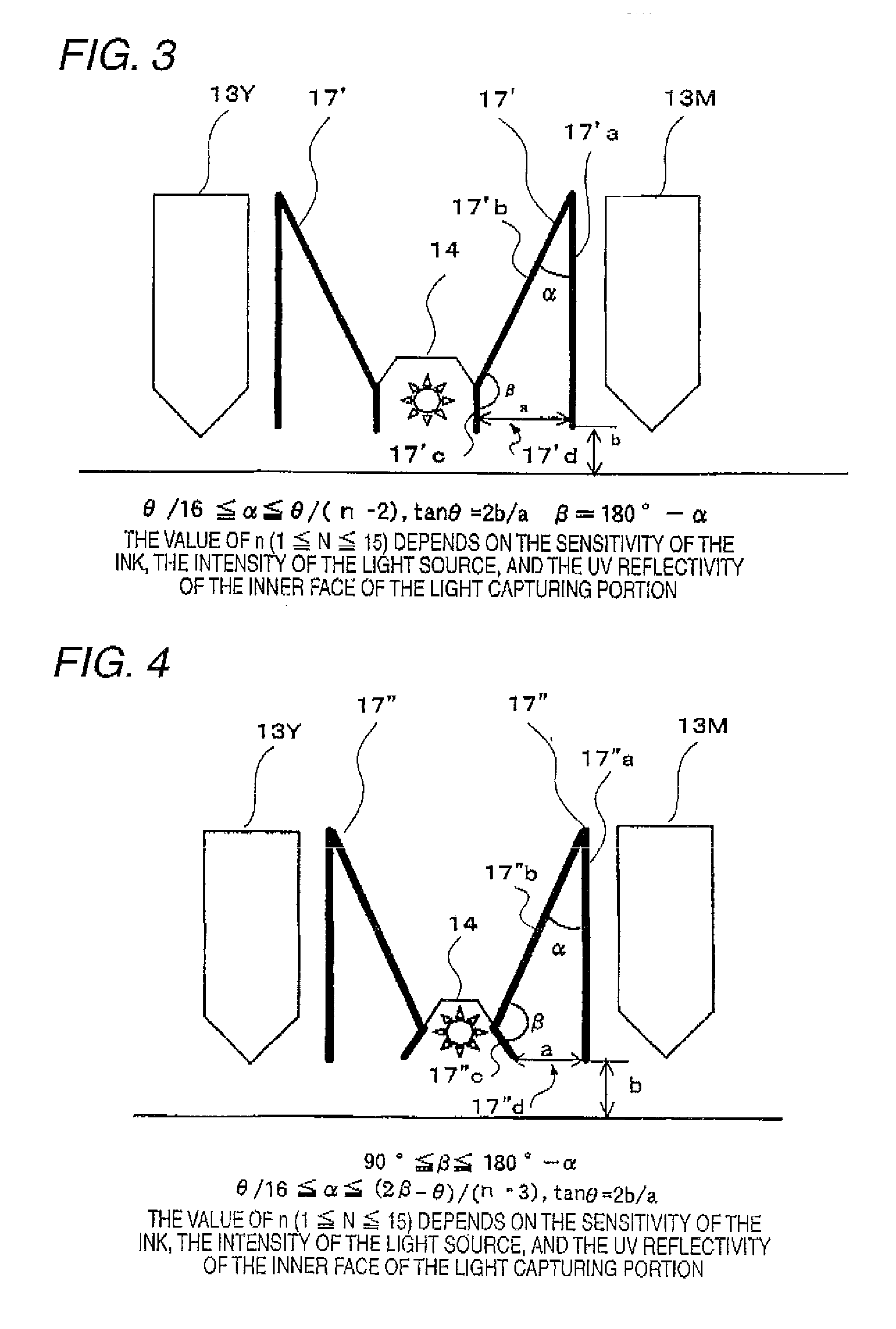
[0070]FIG. 3 is a sectional view illustrating the function of a light capturing portion 17′ in Embodiment 2 of the invention. Referring to FIG. 3, the light capturing portion 17′ is disposed between the UV irradiation lamp 14 and each of the ink-jet heads 13. In a longitudinal section (a section taken parallel to the plane of the figure) taken vertically along the transportation direction of the recording medium S, the light capturing portions 17′ has an wedge (inverted V) shape comprising: a side 17′a vertical to the recording medium S; an oblique side 17′b which is in contact with the top of the vertical side 17′a, and which extends obliquely downward; and a light shielding side 17′c which is in contact with the lower end of the oblique side 17′b, and which extends vertically downward, having no base side, and forming an opening 17′d. When the distance between the both lower ends of the wedge-shaped light capturing portion 17′ in the direction of transporting the recording medium ...

embodiment 3

[0083]FIG. 4 is a sectional view illustrating the function of a light capturing portion 17″ in Embodiment 3 of the invention. Referring to FIG. 4, the light capturing portion 17″c is disposed between the UV irradiation lamp 14 and each of the ink-jet heads 13. In a longitudinal section (a section taken parallel to the plane of the figure) taken vertically along the transportation direction of the recording medium S, the light capturing portions 17″ has an wedge (inverted V) shape comprising: a side 17″a vertical to the recording medium S; an oblique side 17″b which is in contact with the top of the vertical side 17″a, and which extends obliquely downward; and a light shielding side 17″c which is in contact with the lower end of the oblique side 17″b, and which extends obliquely inward, having no base side, and forming an opening 17″d.

[0084]When the distance between the both lower ends of the wedge-shaped light capturing portion 17″ in the direction of transporting the recording med...


PUM


Abstract

A UV curable ink-jet recording apparatus includes: a recording medium transporting unit; an ink-jet head; and a UV irradiating unit, wherein the apparatus includes a light capturing portion between the UV irradiating unit and the ink-jet head, at least a part of the light capturing portion as seen in a longitudinal section taken vertically along a direction of transporting the recording medium has an opened wedge shape having no base side and comprising: a side vertical to the recording medium; and an oblique side which is in contact with a top of the vertical side, and which extends obliquely downward, the vertical side is located on the side of the ink-jet head, and the oblique side downward extends from the top toward the UV irradiating unit.

Description

FIELD OF THE INVENTION[0001]The present invention relates to an ink-jet apparatus in which an ink is ejected onto a recording medium by an ink-jet head to form an image, and more particularly to an ink-jet recording apparatus in which stray light can be captured.BACKGROUND OF THE INVENTION[0002]An ink-jet apparatus in which an ink that can be cured by an active energy ray such as a UV ray (ultraviolet ray) or an electron beam is ejected onto a recording medium with using an ink-jet head, and the ink is cured by active-ray irradiation to form an image has features such as that it is environmentally friendly, and that it can obtain a high-resolution image which can be recorded at a high speed on various recording media, and which hardly bleeds. Particularly, development of an apparatus which uses a UV curable ink is advancing from the viewpoints of easy handling of a light source, compactness, and the like. By taking the advantage of the high-speed fixing property, a so-called single-...

Claims


Application Information

Patent Timeline
Patent Type & Authority Applications(United States)
IPC IPC(8): B41J2/01
CPCB41J11/002B41J11/00214B41J11/00218
Inventor YOKOTA, YASUYO
Owner FUJIFILM CORP
Why Eureka
Try Eureka