Projector and driving method of light source for projector

a technology of projectors and driving methods, applied in the direction of electric variable regulation, process and machine control, instruments, etc., can solve the problems of reducing light utilization efficiency in optical systems disposed downstream from the electrodes, reducing illuminance or flickering, and arc length considerably increasing, so as to prevent flickering and color unevenness, high heat capacity, and high quality

Inactive Publication Date: 2008-12-04
SEIKO EPSON CORP
View PDF2 Cites 19 Cited by
  • Summary
  • Abstract
  • Description
  • Claims
  • Application Information

AI Technical Summary

Benefits of technology

[0024]According to the driving method of the light source for the projector, the step of melting the surface layers of the tip and the surrounding area of the tip extending from the main body of the electrode more greatly damaged in the pair of the first and second electrodes, for example, and the step of expanding the tip of the main body of the one electrode are performed in the restoration mode. Thus, the positions and shapes of the tips of the electrodes

Problems solved by technology

These phenomena lead to instability of the discharge position, causing decrease in illuminance or flickering due to arc shift.
In this case, the arc length considerably increases, and light utilization efficiency lowers in optical systems disposed downstream from the electrodes.
Moreover, because the starting point of discharge is not determined, flicker and arc shift are easily caused.
These conditions lead to flickering—of a projection image or lowering of l

Method used


Image

  • Projector and driving method of light source for projector
  • Projector and driving method of light source for projector
  • Projector and driving method of light source for projector

Examples


Embodiment Construction

[0034]A structure and the like of a projector according to an embodiment of the invention are hereinafter described with reference to the drawings.

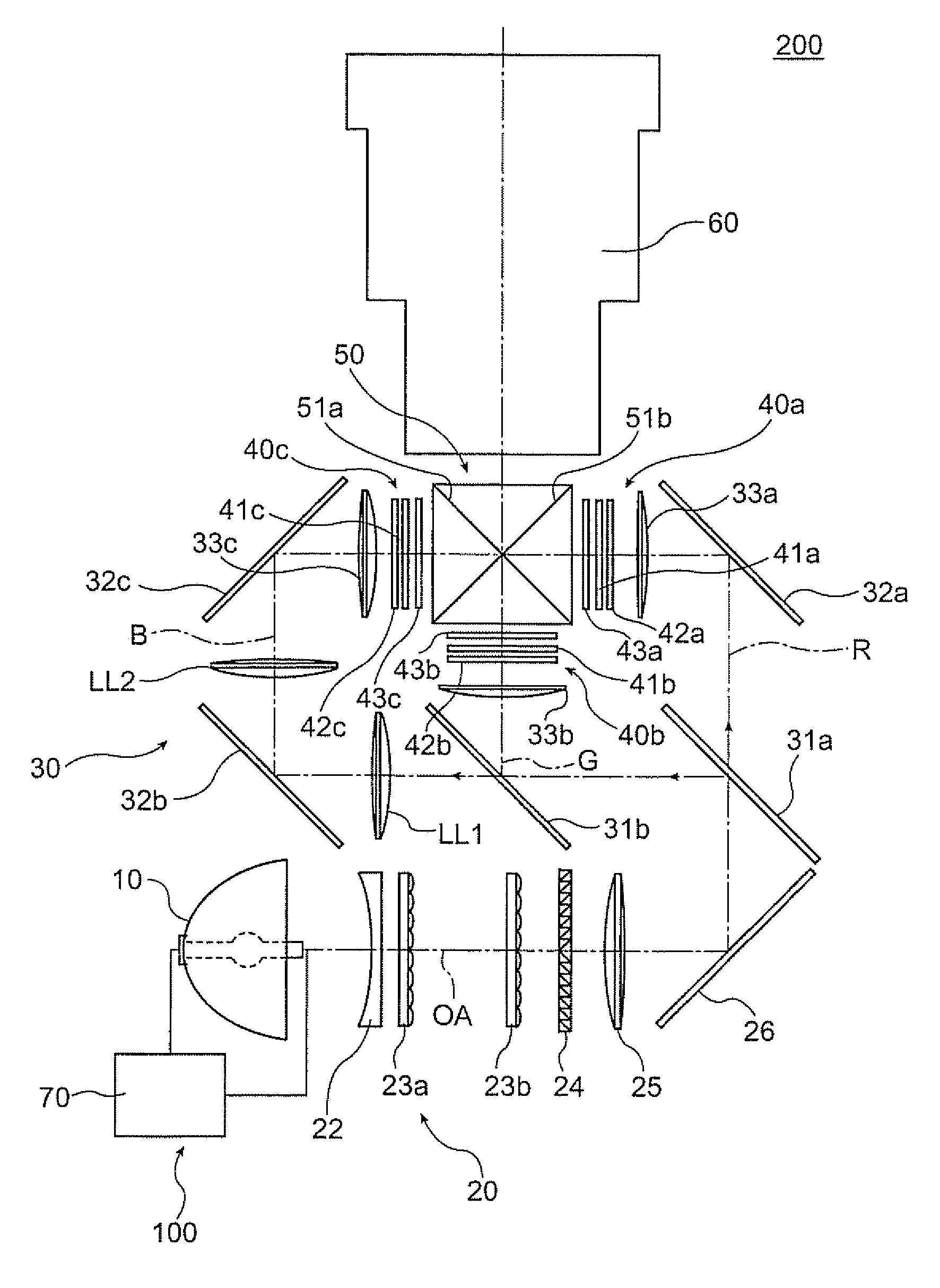
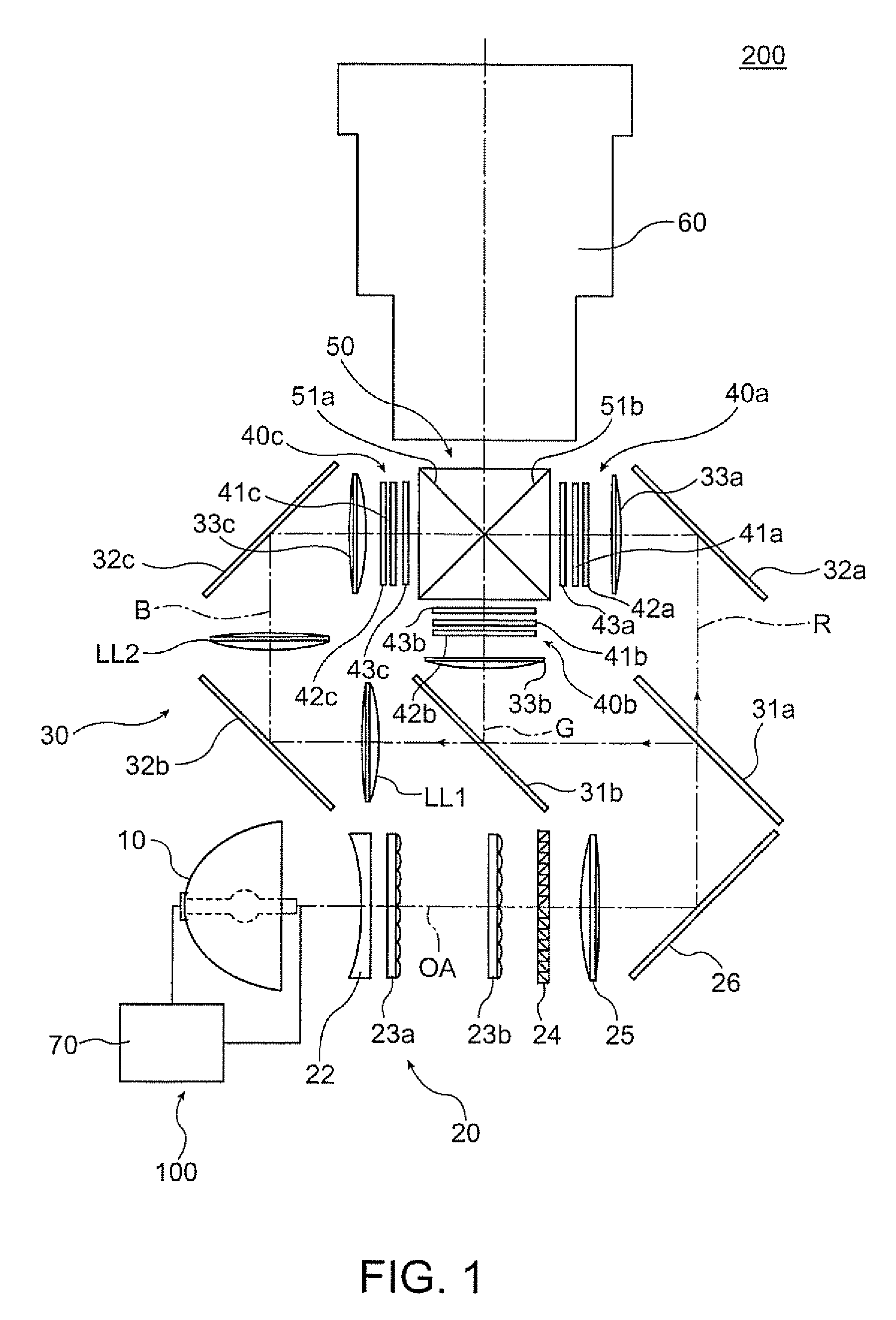
[0035]FIG. 1 illustrates the concept of the structure of the projector in this embodiment. A projector 200 has a light source 100, an illumination system 20, a color separation system 30, liquid crystal light valves 40a, 40b and 40c, a cross dichroic prism 50, and a projection lens 60.

[0036]The light source 100 of the projector 200 has a light source unit 10 and a light source driving system 70, and emits light for illuminating the liquid crystal light valves 40a, 40b and 40c via the illumination system 20 and other components.

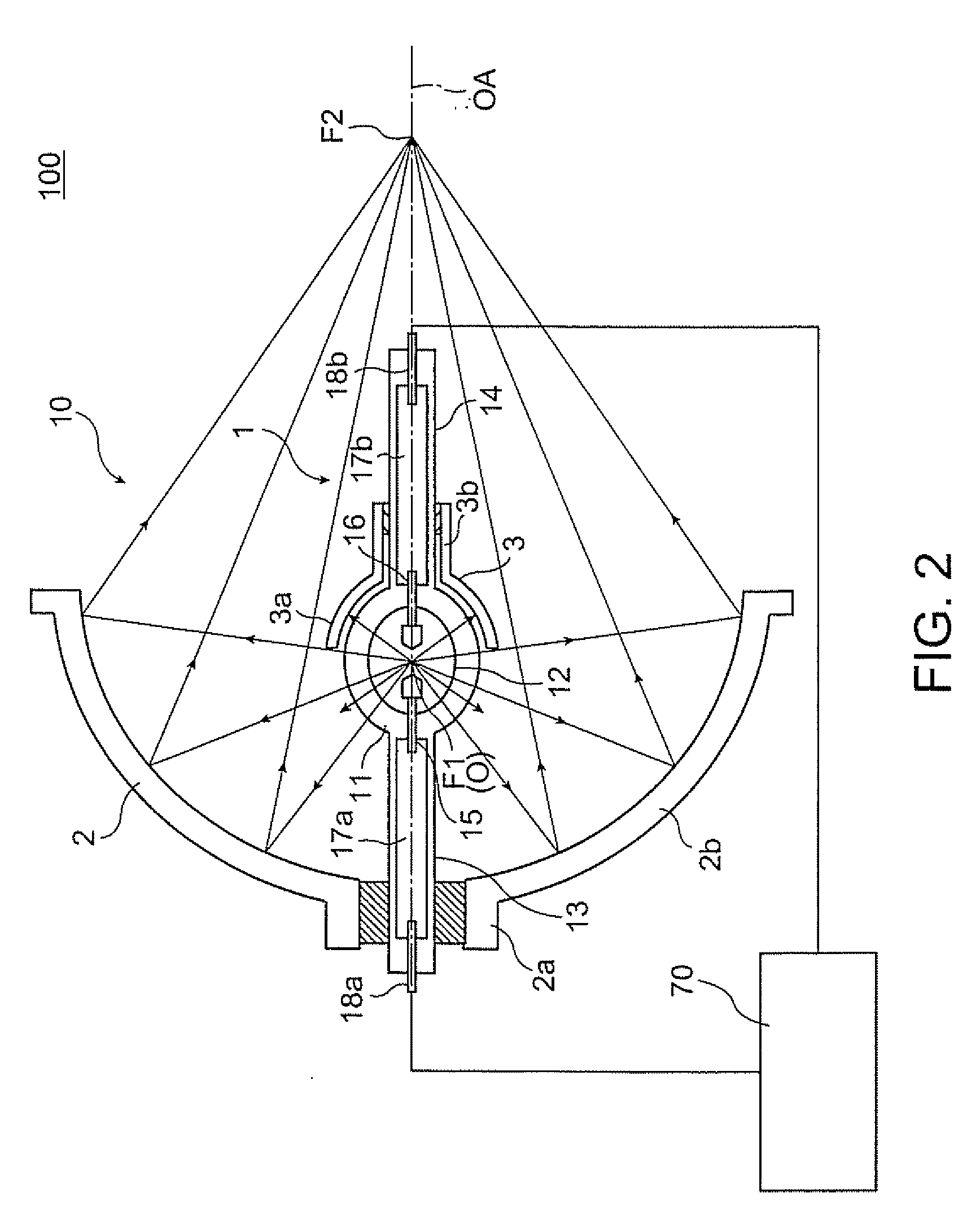
[0037]FIG. 2 is a cross-sectional view schematically illustrating the structure of the light source 100. The light source unit 10 of the light source 100 has a discharge light emission type discharge lamp 1, a reflector 2 as a main elliptic reflection mirror, and a sub mirror 3 as a spherical sub reflection mirror. ...


PUM


Abstract

A projector includes an discharge lamp which has a first electrode and a second electrode and emits light by generating discharge between the first and second electrodes, and a driving system which supplies power by alternating polarities of the first electrode and the second electrode. The driving system is operable in a restoration mode. The driving system melts surface layers of a tip and a surrounding area of the tip extending from a main body of one of the first and second electrodes, and expands a new tip on a tip area of the main body of the one electrode in the restoration mode.

Description

[0001]This application claims priority from Japanese Patent Application No. 2007-147745 filed in the Japanese Patent Office on Jun. 4, 2007, the entire disclosure of which is hereby incorporated by reference in its entirety.BACKGROUND[0002]1. Technical Field[0003]The present invention relates to a projector which includes a discharge light emission type light source having a pair of electrodes and a driving method of a light source for a projector.[0004]2. Related Art[0005]According to a discharge lamp lighting device for a projector which uses a high pressure discharge lamp, it is known that a projection is formed on the tip surface of each electrode of the lighting device during light emission. However, in such a condition where the lighting device continuously emits light for a long period, a plurality of such projections may be formed or the tip surface of the electrode may be even concaved or convexed. These phenomena lead to instability of the discharge position, causing decre...

Claims


Application Information

Patent Timeline
IPC IPC(8): G03B21/14H05B41/36
CPCG03B21/2026G03B21/206H05B41/2928Y02B20/208Y02B20/00
Inventor YAMAUCHI, KENTAROSOMA, SHIGEYASU
Owner SEIKO EPSON CORP
Why Eureka
Try Eureka