

Planar lighting device
a lighting device and planar technology, applied in the direction of lighting and heating equipment, instruments, mechanical equipment, etc., can solve the problems of the distance that light can travel, and the inability so as to reduce the thickness and weight of the planar lighting device, the effect of increasing the dimension
- Summary
- Abstract
- Description
- Claims
- Application Information
AI Technical Summary
Benefits of technology
Problems solved by technology
Method used
Image

Examples
Embodiment Construction
[0063]The planar lighting device of the invention will be described in detail below referring to an embodiment illustrated in the accompanying drawings.
[0064]Now, a first example of the invention will be described first.
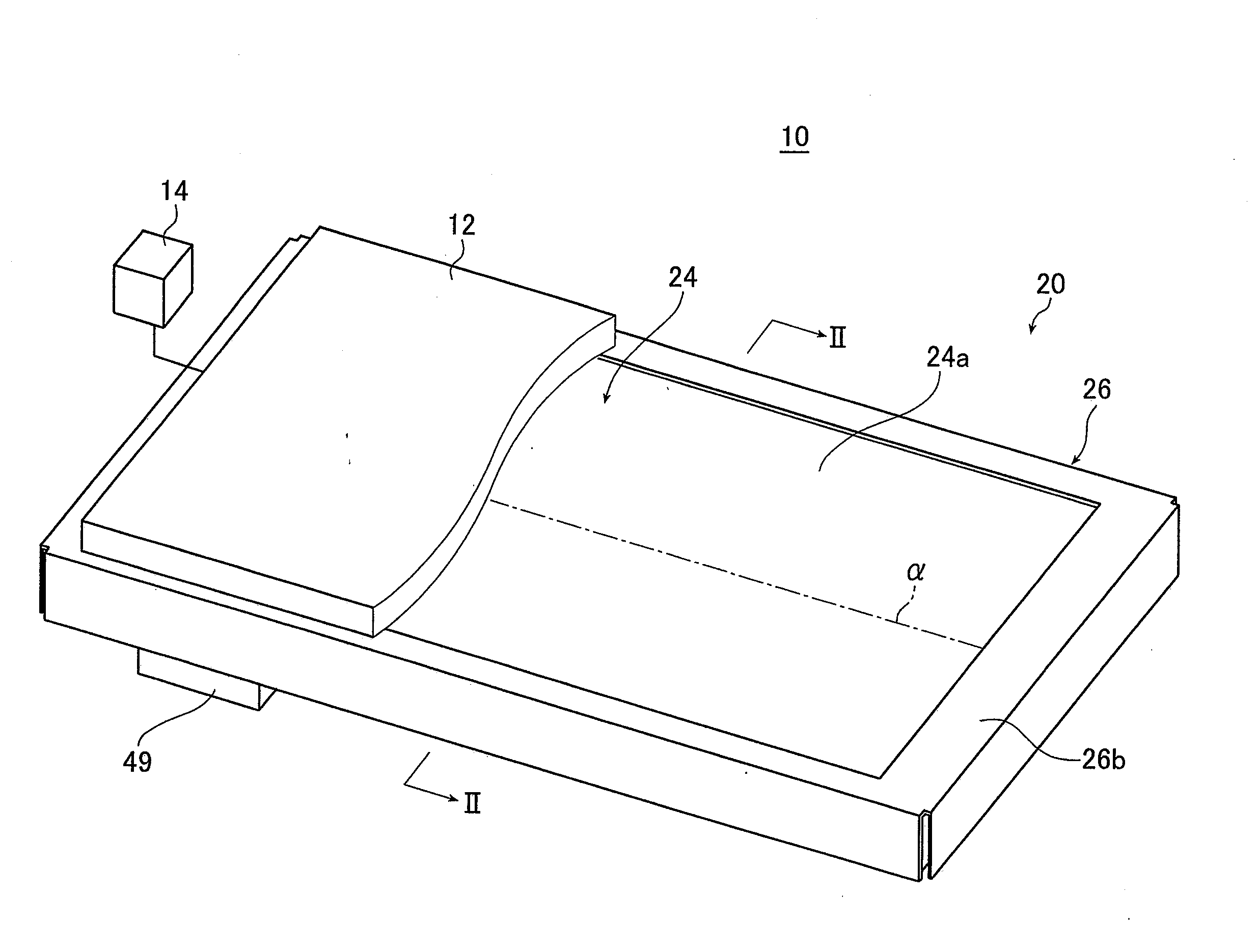
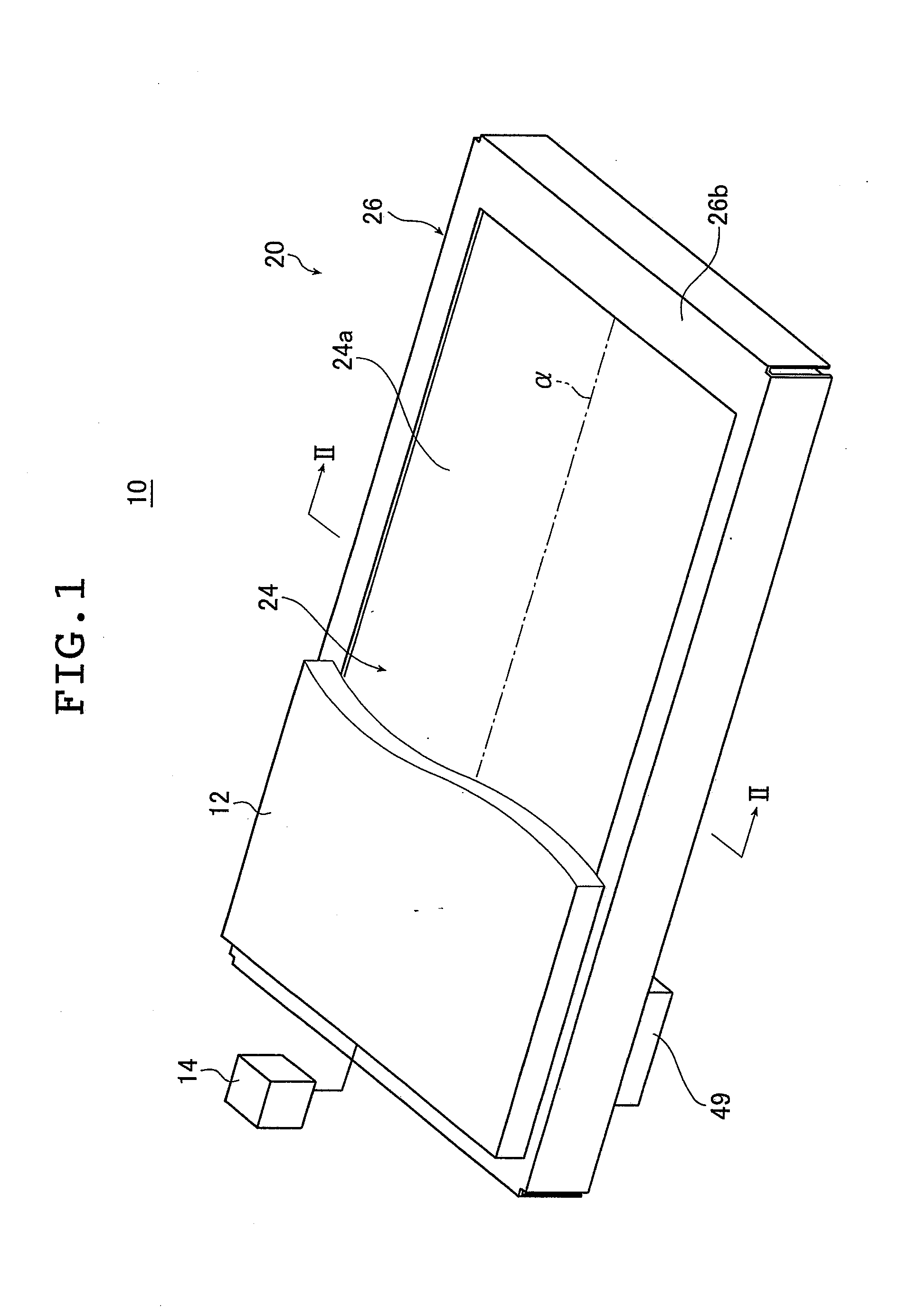
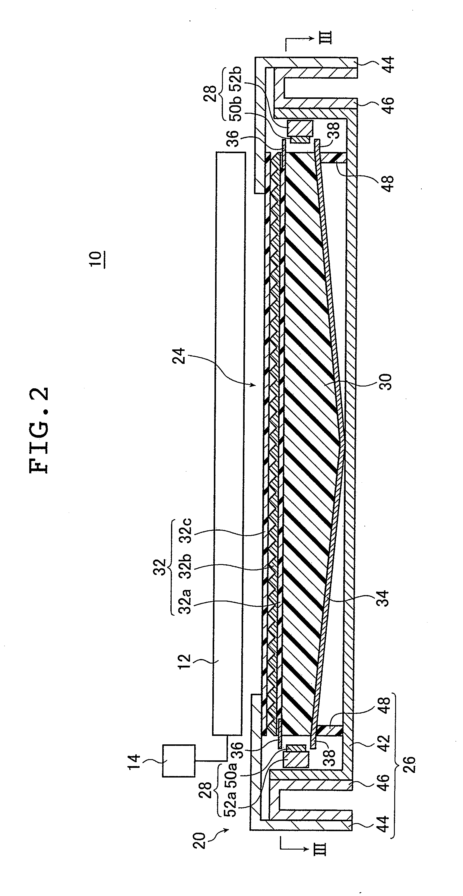
[0065]FIG. 1 is a schematic perspective view illustrating a liquid crystal display device provided with the planar lighting device of the invention; FIG. 2 is a cross sectional view of the liquid crystal display device illustrated in FIG. 1 taken along line II-II.
[0066]FIG. 3A is a view of the planar lighting device (also referred to as “backlight unit” below) illustrated in FIG. 2 taken along line III-III; FIG. 3B is a cross sectional view of FIG. 3A taken along line B-B.
[0067]A liquid crystal display device 10 comprises a backlight unit 20, a liquid crystal display panel 12 disposed on the side of the backlight unit closer to the light exit plane, and a drive unit 14 for driving the liquid crystal display panel 12. In FIG. 1, part of the liquid crystal display pane...
PUM
 Abstract
Description
Claims
Application Information