Aircraft wing with extendible nose flap

a technology of aircraft wings and nose flaps, applied in the field of aircraft wings, can solve the problems of disadvantageous spindle drive rods, system generally having a high structural weight, and inability to represent the rotation path of the aircraft, and achieve the effect of facilitating maintenance and great variability

Active Publication Date: 2009-01-01
AIRBUS DEFENCE & SPACE
View PDF1 Cites 18 Cited by
  • Summary
  • Abstract
  • Description
  • Claims
  • Application Information

AI Technical Summary

Benefits of technology

[0009]The present invention is directed to an aircraft wing with an extendible nose flap, which provides an improvement over known systems that cost too much in terms of space and weight. Implementations of the invention provi

Problems solved by technology

A problem exists in that, with the split nose flaps, the necessary path of motion cannot be represented as rotation about a support point located on the wing.
However, such systems have corresponding demands on the extension geometry of the actuating mechanism that must be met.
However, these systems with spindle drive rods are disadvantageous because they occupy considerable space in the direction of the wing structure.
Furthermore, due to the length of the spind

Method used


Image

  • Aircraft wing with extendible nose flap
  • Aircraft wing with extendible nose flap
  • Aircraft wing with extendible nose flap

Examples


Embodiment Construction

[0037]The particulars shown herein are by way of example and for purposes of illustrative discussion of the embodiments of the present invention only and are presented in the cause of providing what is believed to be the most useful and readily understood description of the principles and conceptual aspects of the present invention. In this regard, no attempt is made to show structural details of the present invention in more detail than is necessary for the fundamental understanding of the present invention, the description taken with the drawings making apparent to those skilled in the art how the several forms of the present invention may be embodied in practice.

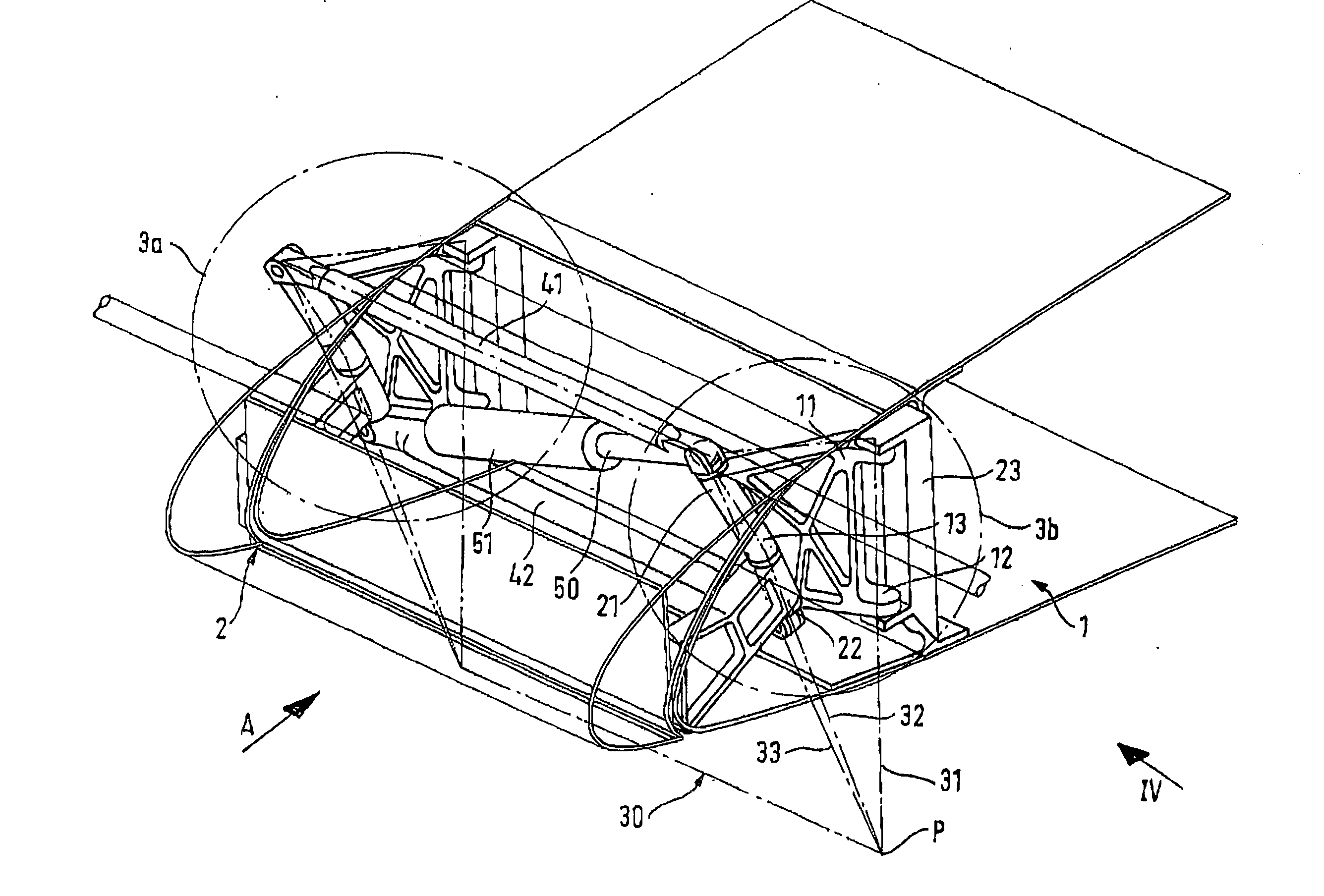
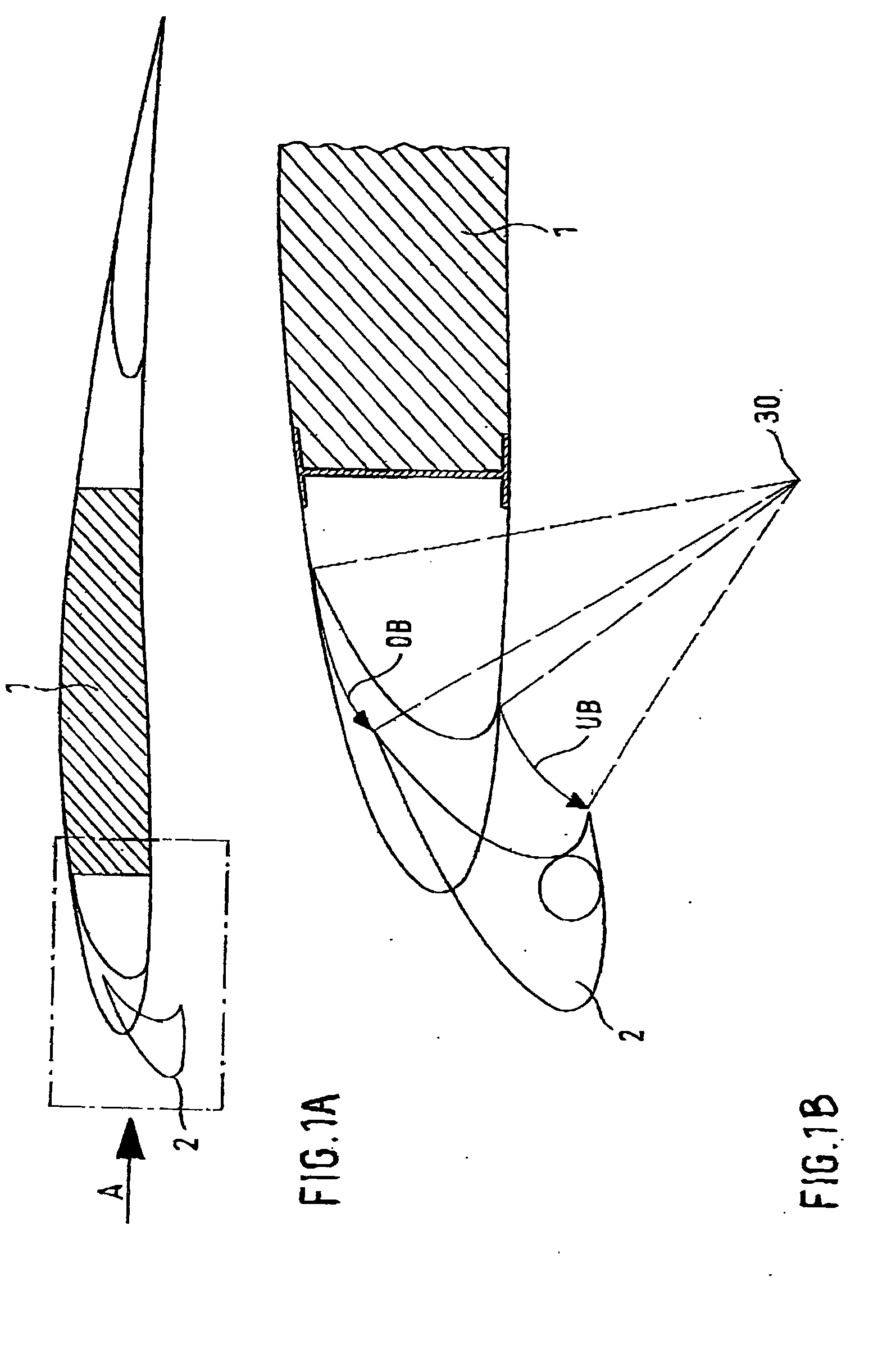
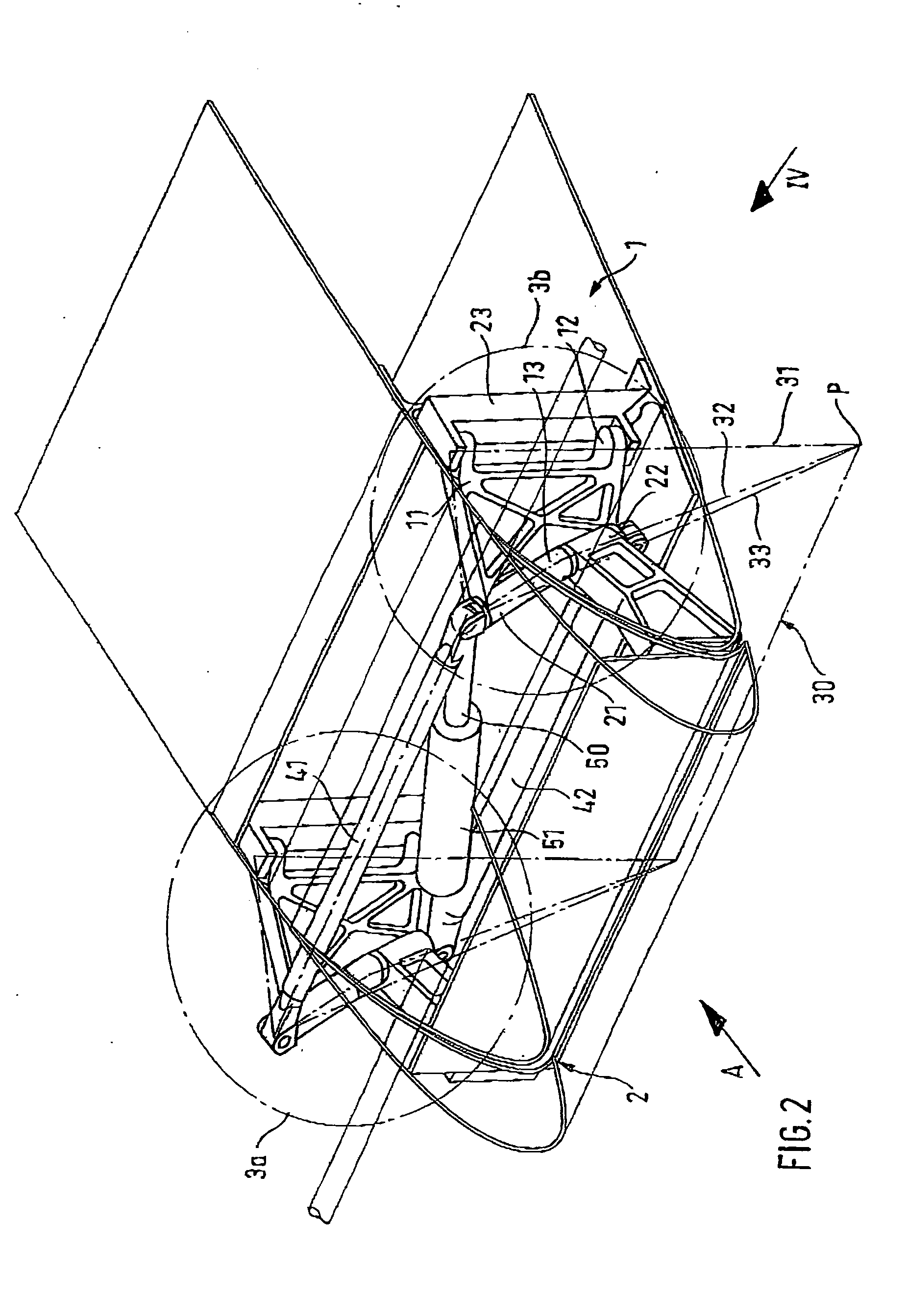
[0038]An aircraft wing with extendible nose flap 2 is shown diagrammatically in cross section in FIG. 1A. The fixed part of the wing is labeled wing box 1, and the incident flow is labeled A. FIG. 1B shows an enlargement of the section of the aircraft wing shown by a dash-dot line in FIG. 1A. The wing box 1, in which fuel...


PUM


Abstract

An aircraft wing including a wing box and a nose flap moveably connected to the wing box by first and second folding hinges. A first transverse link is pivotally connected to first portions of the first and second folding hinges. A second transverse link is pivotally connected to second portions of the first and second folding hinges. An actuator is connected diagonally between the first and second transverse links for moving the nose flap between a retracted position and an extended position. The instant abstract is neither intended to define the invention disclosed in the specification nor intended to limit the scope of the invention in any way.

Description

CROSS-REFERENCE TO RELATED APPLICATIONS[0001]The present application claims priority under 35 U.S.C. §119 of German Patent Application No. 10 2005 044 549.7, filed on Sep. 17, 2005, the disclosure of which is expressly incorporated by reference herein in its entirety.BACKGROUND OF THE INVENTION[0002]1. Field of the Invention[0003]The present invention relates to an aircraft wing with a wing box and at least one nose flap that is moveable, about a nose swivel axis lying crosswise to the incident flow and outside the wing structure, between a starting position bearing against the wing box and an operating position spaced in front of the wing box.[0004]2. Discussion of Background Information[0005]With almost all aircraft according to the prior art, extendible nose flaps on the aircraft wings are used to increase uplift, particularly in high angle of attack situations. Various embodiments of such flaps are known in the prior art, such as, for example, “droop nose flaps,”“Kröger flaps” o...

Claims


Application Information

Patent Timeline
IPC IPC(8): B64C9/00
CPCY02T50/44B64C9/22Y02T50/40
Inventor PEREZ-SANCHEZ, JUAN
Owner AIRBUS DEFENCE & SPACE
Why Eureka
Try Eureka