Push-button switch and electronic apparatus having the same

Inactive Publication Date: 2009-04-09
PANASONIC CORP
View PDF5 Cites 8 Cited by
  • Summary
  • Abstract
  • Description
  • Claims
  • Application Information

AI Technical Summary

Benefits of technology

[0025]According to the push button switch of the present invention, effect of heat soak of the substrate can be increased by sufficient heat radiation along the surface of the substrate through the heat conducting layer extending along the substrate. In addition, it becomes possible to broadly diffuse heat from the heat generating part on the substrate along the surface of the substrate by means of the heat conducting layer in the vicinity of the substrate.
[0026]According to the electronic apparatus of the present invention, the substrate with many mounted electronic parts can be more efficiently heat soaked in every direction along the surface of the substrate by the heat conducting layer extending along the substrate. The heat conducting layer positioned in the vicinity of the surface of the substrate enables to broadly diffuse heat from the heat generating part and the like on the substrate in every direction along the surface of the substrate so as to remarkably increase efficiency of radiation of the heat. Consequently, it becomes possible to provide an electronic apparatus capable of preventing the local heating of its chassis resulting from the high temperature rise of the heat generating part and other surrounding parts.
[0027]Furthermore, it is also possible to reduce the thickness of the electronic apparatus and improve the click feeling and the like of the push button switch in the case that the heat conducting layer has an opening portion corresponding to the click portion of the electrically insulating layer.

Problems solved by technology

The electronic apparatus comprising the aforementioned push button switches, however, encounters the difficulties in increasing efficiency of heat soak of the chassis or body including the substrate 121 having the heat generating part 129 mounted thereon due to the fact that the respective heat radiating layers of the key tops 122b of the key sheet 122 are separate and independent from one another.
For this reasons, it is difficult to assuredly prevent the chassis of the electronic apparatus from being heated partly to high temperature.
These also make it difficult to increase the efficiency of heat radiation through the heat radiating layers in order to decrease the temperature of the heat generating part 129 and other surrounding parts mounted in the vicinity of the heat generating part 129.

Method used


Image

  • Push-button switch and electronic apparatus having the same
  • Push-button switch and electronic apparatus having the same
  • Push-button switch and electronic apparatus having the same

Examples


first embodiment

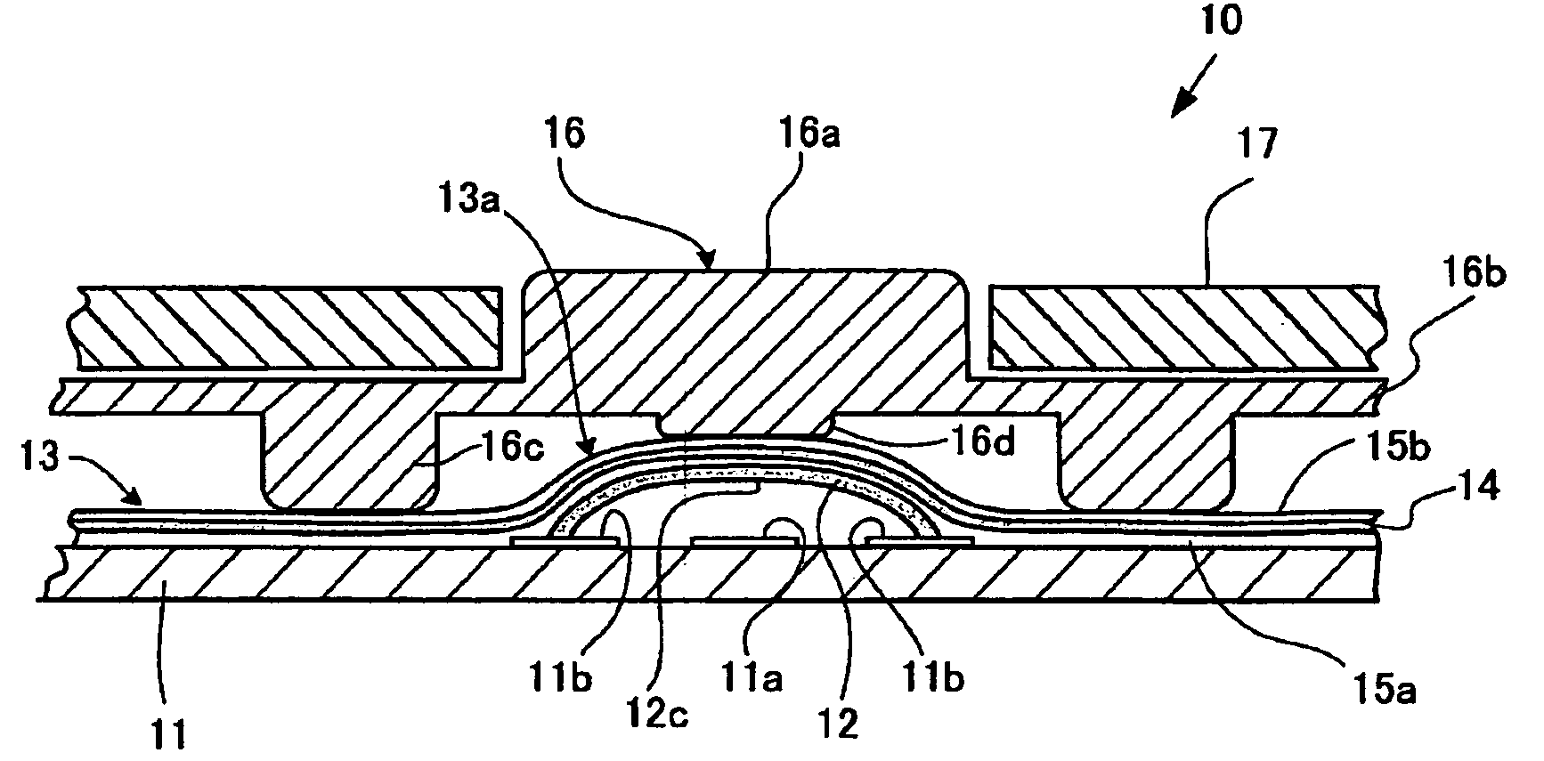
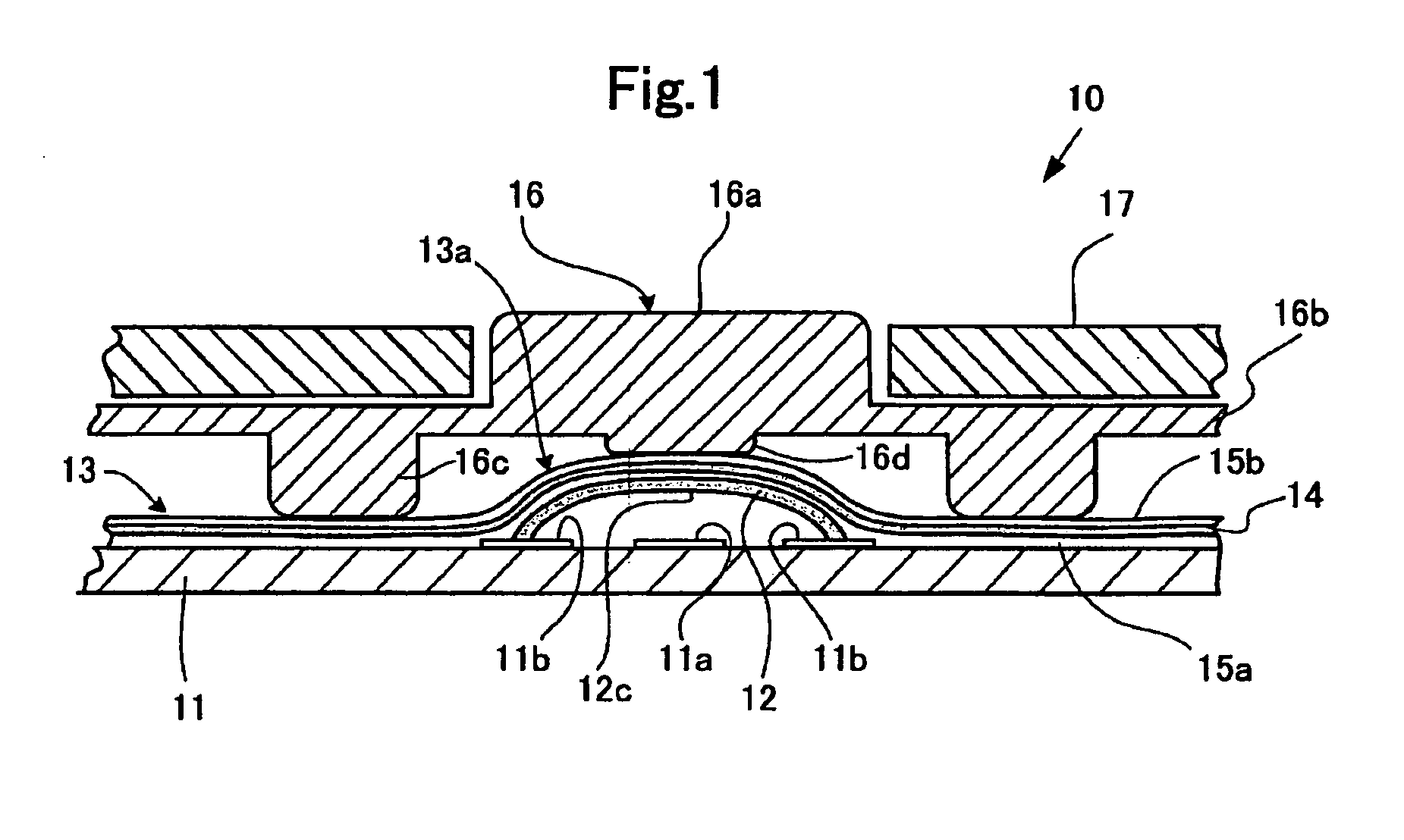
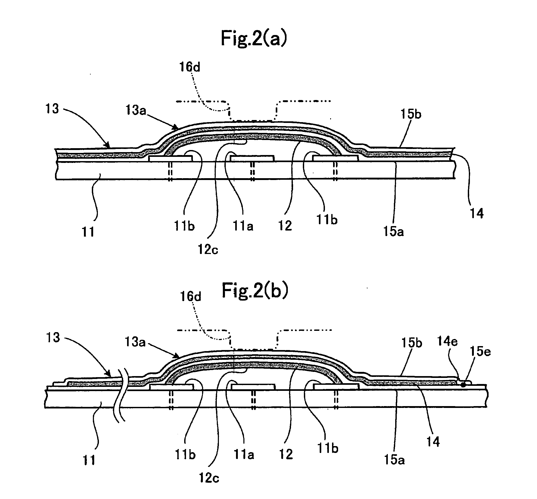
[0067]FIGS. 1-6 show a first embodiment of the electronic apparatus according to the present invention.

[0068]The present embodiment is exemplified in a preferred electronic apparatus 1, as comprising a compact and thin type chassis 17 and a plurality of push button switches 10 each provided in the chassis 17 as shown in FIG. 3. The electronic apparatus 1 in appearance has an exterior the same as or similar to that of the conventional mobile phone shown in FIG. 15. The electronic apparatus 1 may be any one of other compact and thin portable / mobile electronic apparatuses such as for example a PDA (Personal Digital Assistant).

[0069]As shown in FIG. 1, each of the push button switches 10 according to the present embodiment comprises, on a printed circuit substrate 11, a first contacting part 11a and a second contacting part 11b operable to be brought into electrical conduction with the first contact 11a, and a flexible electrically insulating sheet 13 (i.e., an electrically insulating l...

second embodiment

[0095]FIGS. 7-9 show a second embodiment of the electronic apparatus according to the present invention.

[0096]The electronic apparatus according to the present embodiment is a compact and thin portable electronic apparatus equipped with a plurality of push button switches 20 in the chassis in the same manner as in the aforementioned first embodiment. This electronic apparatus in appearance has an exterior the same as or similar to that of the conventional mobile phone shown in FIG. 15. Here, the constituent elements the same as those in the aforementioned first embodiment bear their respective reference numerals the same as those shown in FIGS. 1 to 4, and are omitted in detailed description thereof.

[0097]As shown in FIG. 7, each of the push button switches 20 according to the present embodiment comprises, on the printed circuit substrate 11, the first contacting part 11a and the second contacting part 11b operable to be brought into electrical conduction with the first contact 11a,...

third embodiment

[0108]FIG. 10 and FIG. 11 in combination show a third embodiment of the electronic apparatus according to the present invention.

[0109]The electronic apparatus according to the present embodiment is a compact and thin portable electronic apparatus equipped with a plurality of push button switches 30 in the chassis in the same manner as in the aforementioned first embodiment. This electronic apparatus in appearance has an exterior the same as or similar to that of the conventional mobile phone shown in FIG. 15. The constituent elements the same as those in the aforementioned first embodiment bear their respective reference numerals the same as those shown in FIGS. 1 to 4, and are omitted in detailed description thereof.

[0110]As shown in FIGS. 10(a) and 10(b), each of the push button switches 30 according to the present embodiment comprises, on the printed circuit substrate 11, the first contacting part 11a and the second contacting part 11b operable to be brought into electrical condu...


PUM


Abstract

To prevent the local heating of an electronic apparatus chassis, there is provided a push button switch (10), which comprises a substrate (11) having a first contacting part (11a) and a second contacting part (11b) operable to be brought into electrical conduction with the first contacting part (11a), and a flexible electrically insulating sheet (13) covering the substrate (11) and having a click portion (13a) on the inside of which the first and second contacting parts are disposed to be brought into and out of electrical conduction therebetween in response to depression of the click portion. The electrically insulating sheet (13) includes a heat conducting layer (14) extending along the substrate (11).

Description

TECHNICAL FIELD[0001]The present invention relates to a push button switch and an electronic apparatus having the same, and more particularly to a push button switch improved in heat soak and heat radiation characteristics to be proper for portable electronic apparatuses, and an electronic apparatus having the improved push button switch.BACKGROUND ART[0002]Recently it has been strictly required that electronic apparatuses, especially portable electronic apparatuses are reduced in volume and body thickness and multi-functionalized, and that each of the portable electronic apparatuses includes in its chassis / body a high density mounted substrate having a plurality of electronic parts but improved in efficiency of heat radiation from the mounted electronic parts.[0003]One of the electronic apparatuses of such type is shown in FIGS. 15-17 as a mobile phone. (See Patent Document 1 or the like.) As shown in FIG. 15, this electronic apparatus 10 comprises a lower side body 101 including a...

Claims


Application Information

Patent Timeline
IPC IPC(8): H01H13/14
CPCH01H9/52H01H13/704H01H2205/026H01H2205/03H01H2239/072H01H2209/014H01H2221/002H01H2231/022H01H2239/008H01H2209/002
Inventor ICHIKAWA, YOHEINAKANISHI, KIYOSHI
Owner PANASONIC CORP
Why Eureka
Try Eureka