Image forming apparatus and control method thereof

a technology of image forming apparatus and control method, which is applied in the direction of electrographic process apparatus, instruments, optics, etc., can solve the problems of increasing or decreasing the toner consumption, increasing the toner amount used for image forming operation, and reducing the toner consumption. , to achieve the effect of reducing the consumption of toner and improving the halftone realization

a technology of image forming apparatus and control method, which is applied in the direction of electrographic process apparatus, instruments, optics, etc., can solve the problems of increasing or decreasing the toner consumption, increasing the toner amount used for image forming operation, and reducing the toner consumption. , to achieve the effect of reducing the consumption of toner and improving the halftone realization

US20090110422A1Inactive Publication Date: 2009-04-30S PRINTING SOLUTION CO LTD

Image

  • Image forming apparatus and control method thereof
  • Image forming apparatus and control method thereof
  • Image forming apparatus and control method thereof

Examples


Embodiment Construction

[0050]Reference will now be made in detail to embodiments of the present general inventive concept, examples of which are illustrated in the accompanying drawings, wherein like reference numerals refer to the like elements throughout. The embodiments are described below in order to explain the present general inventive concept by referring to the figures.

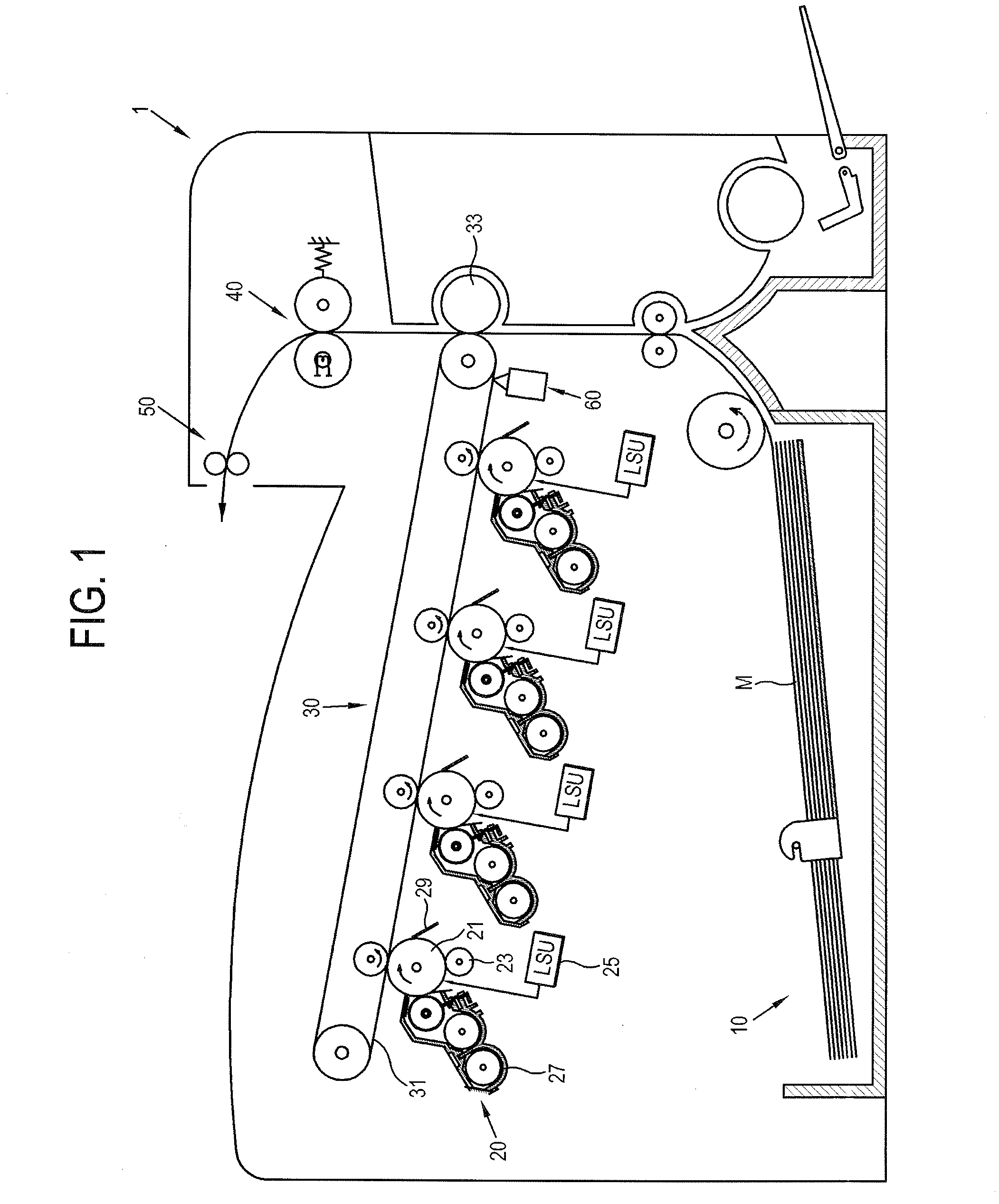
[0051]FIG. 1 illustrates an electrophotographic color printer applying an image forming apparatus according to an exemplary embodiment of the present general inventive concept.

[0052]As illustrated therein, an electrophotographic color printer 1 includes a medium supply unit 10 to supply a print medium M, an image forming unit 20 to form a color image on the supplied print medium M with an electrophotographic method, a transfer unit 30 to transfer the formed color image to the print medium M, a fusing unit 40 to fuse a toner image transferred to the print medium M and a medium discharging unit 50 to discharge the print medium M.

[0053...


PUM


Abstract

An image forming apparatus includes a density detector to detect a density of an image to be printed, and an image density controller to adjust a toner supply amount and a developing bias based on a detection result of the density detector to thereby adjust a density of the image.

Description

CROSS-REFERENCE TO RELATED APPLICATIONS[0001]This application claims priority under 35 U.S.C. §119(a) from Korean Patent Application No. 10-2007-0107782, filed on Oct. 25, 2007, in the Korean Intellectual Property Office, the disclosure of which is incorporated herein by reference in its entirety.BACKGROUND OF THE INVENTION[0002]1. Field of the Invention[0003]The present general inventive concept relates to an image forming apparatus to control a density of a toner supplied by a developing unit and a control method thereof, and more particularly, to an image forming apparatus which reduces consumption of a toner used to detect a density of a toner and improves halftone realization to thereby control a density of a supplied toner, and a control method thereof.[0004]2. Description of the Related Art[0005]Generally, a bi-component type image forming apparatus forms a toner image on a print medium with a developer having a toner forming an image and a carrier carrying the toner by a mag...

Claims


Application Information

Patent Timeline
30 Apr 2009
Publication
US20090110422A1
IPC
G03G15/06
CPC
G03G15/065; G03G2215/00059; G03G15/0849; G03G15/0131; G03G15/5058; G03G2215/0634; G03G15/08; G03G15/00
Inventors
SHINICHI, HISATOMI