Cartridge assembly and shutter assembly for image forming apparatus

a technology of image forming apparatus and shutter assembly, which is applied in the direction of electrographic process apparatus, instruments, optics, etc., can solve the problems of large amount of developer abandoned, degraded image quality, and degraded image quality, so as to reduce the size of the image forming apparatus, reduce the amount of toner consumption, and prevent the quality of the printed image from being degraded

Active Publication Date: 2016-03-03
SINDOH
View PDF2 Cites 6 Cited by
  • Summary
  • Abstract
  • Description
  • Claims
  • Application Information

AI Technical Summary

Benefits of technology

[0024]According to the present invention, it is possible to reduce toner consumption and to prevent the quality of the printed image from being degraded. Also, since the developer collecting unit is integrally formed with the drum unit, an entire size of the image forming apparatus can be reduced, and also the waste developer can be easily managed.

Problems solved by technology

However, in such a developer replenishing or replacing method, a large amount of the developer is abandoned, and a separate waste developer receiving part is required.
However, according to patent document 1, a toner consumption may be reduced by collecting and reusing the toner, but there is a problem in that the quality of an image is degraded over time by reduction of the carrier and deterioration of the developer which result from long-term use.
However, in Patent document 2, since there is not a separate developer discharging structure other than a structure for scraping the developer remaining in the drum and collecting the developer, there is a problem in that the quality of an image is degraded by deterioration of the developer due to long-term use, and a separate toner and carrier receiving part is required.
That is, in the conventional image forming apparatus, there is a problem in that the developer leaks when the units or the unit and the main body are detach from each other.

Method used


Image

  • Cartridge assembly and shutter assembly for image forming apparatus
  • Cartridge assembly and shutter assembly for image forming apparatus
  • Cartridge assembly and shutter assembly for image forming apparatus

Examples


Embodiment Construction

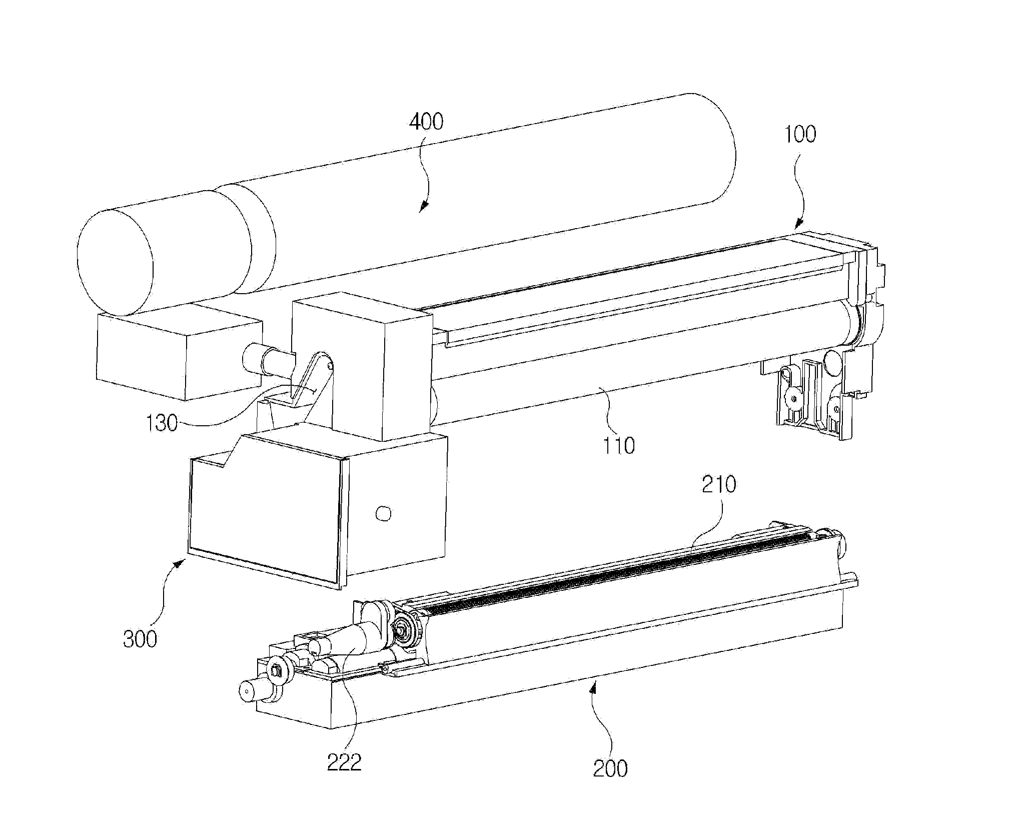
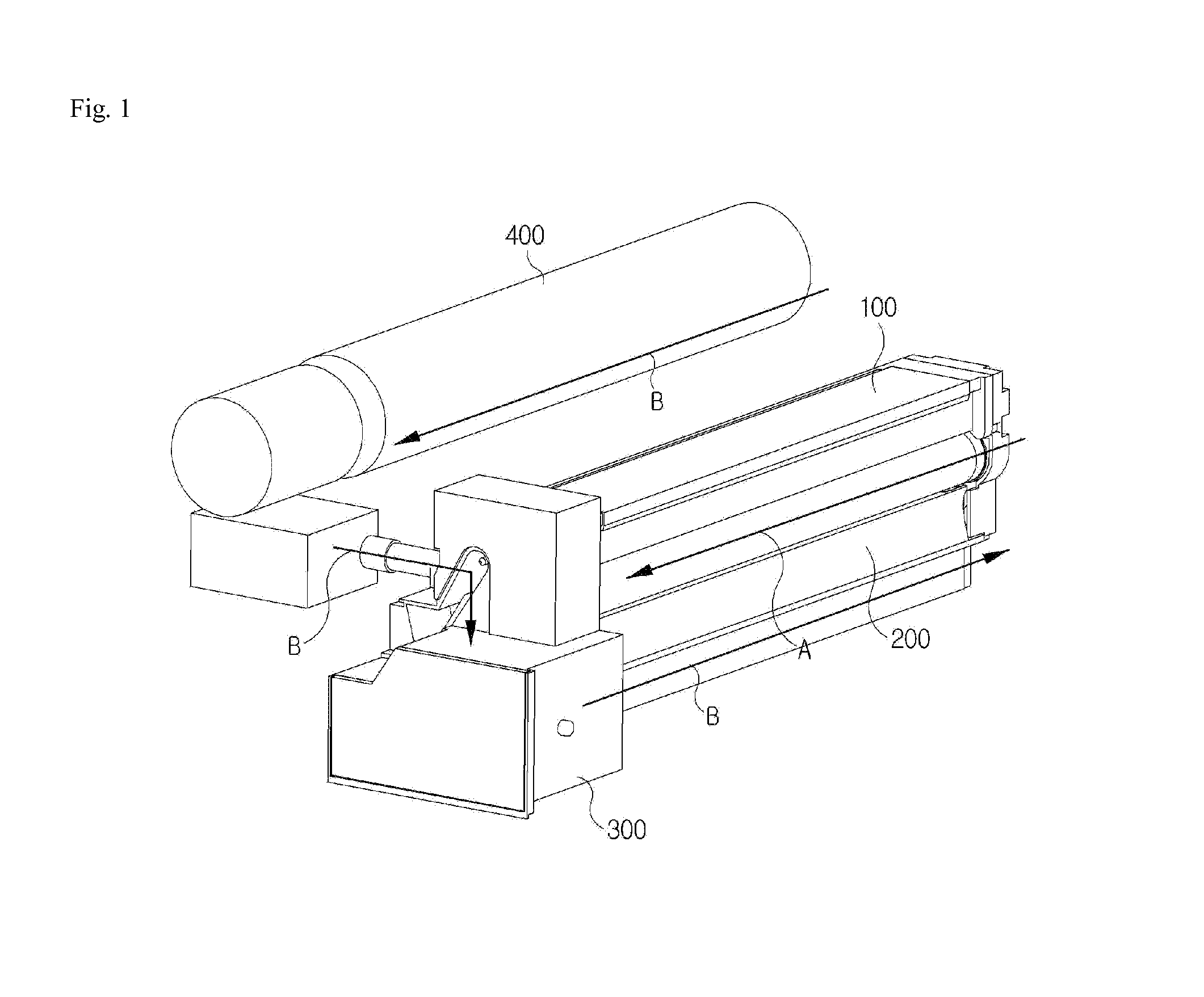
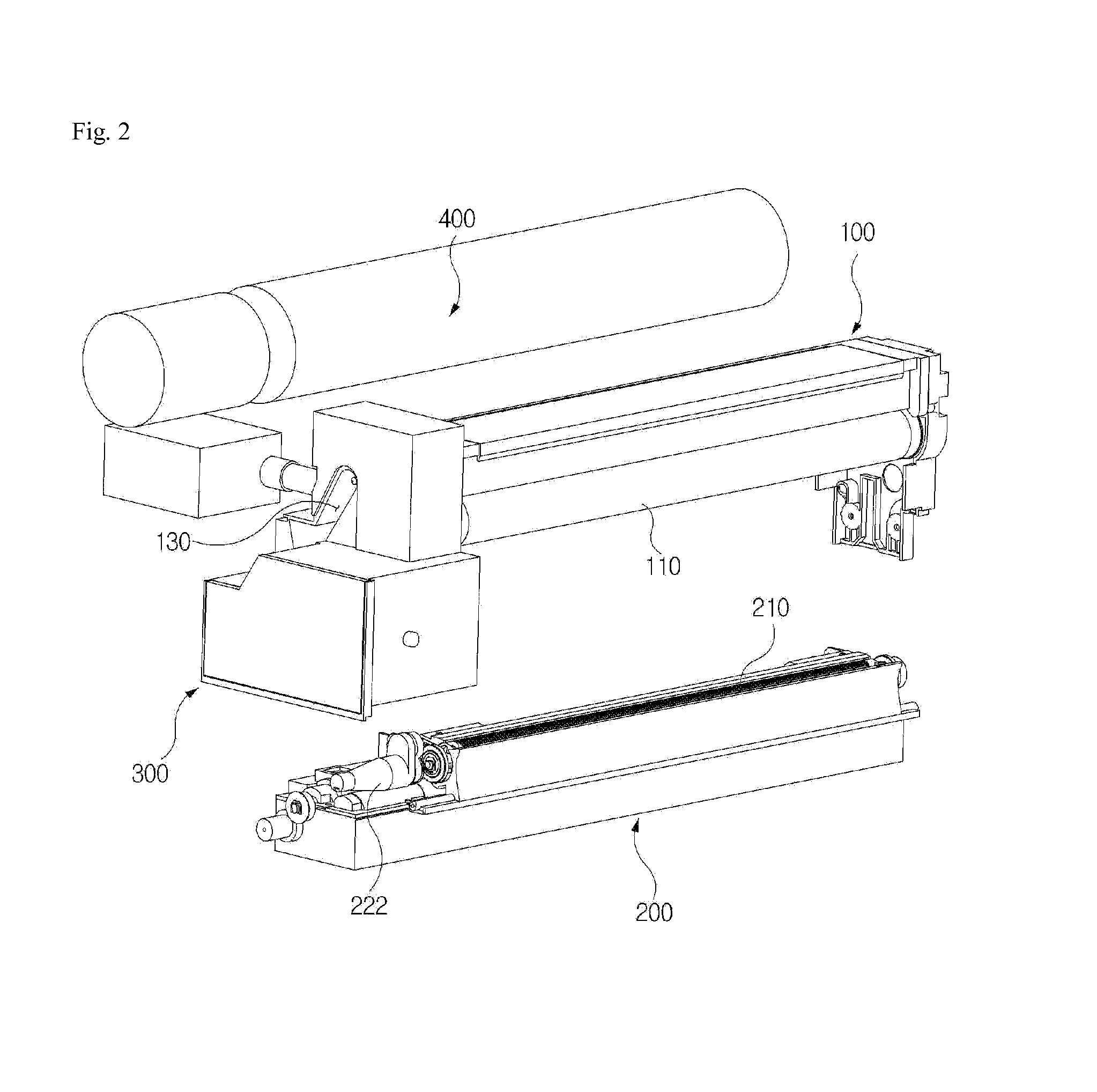
[0039]Referring to FIGS. 1 to 3, a cartridge assembly for an image forming apparatus according to the present invention includes a drum unit 100 and a developing unit 200 which are installed at an inside of the image forming apparatus to form an image, and a developer collecting unit 300 which collects a developer in the developing unit 200.

[0040]The drum unit 100 includes components such as a photosensitive drum, a charging roller and a transfer roller to form a latent image. Also, the drum unit 100 includes a waste toner conveying means 120 which conveys waste toner collected from a surface of the photosensitive drum 110 to one side of the drum unit 100.

[0041]The developing unit 200 is provided with a developing roller 210 which supplies the developer to the latent image formed on the photosensitive drum 110, and also coupled with the drum unit 100 so that the developing roller 210 is in contact with the photosensitive drum 110 of the drum unit 100. Also, the developing unit 200 i...


PUM


Abstract

Provided is a cartridge assembly for an image forming apparatus, including a drum unit provided with a waste toner conveying means which conveys waste toner collected from a surface of a photosensitive drum to one side; a developing unit connected with the drum unit, configured to receive the waste toner collected from the drum unit, and having a developer discharging means to discharge a developer therein to an outside; and a developer collecting unit integrally formed with the drum unit at one side of the drum unit, and configured to collect the developer discharged by the developer discharging means of the developing unit, wherein the drum unit includes a toner injecting means which connects the waste toner conveying means, a new toner supply unit and the developing unit so that the waste toner conveyed by the waste toner conveying means and new toner supplied from the new toner supply unit are injected together into the developing unit. Since the waste toner may be reused together with new toner and the developer may also be discharged, it is possible to reduce toner consumption and to prevent the quality of a printed image from being degraded.

Description

TECHNICAL FIELD[0001]The present invention relates to a cartridge assembly and a shutter assembly for an image forming apparatus.BACKGROUND ART[0002]An image forming apparatus such as a copy machine, a printer and a multifunction printer is classified into an ink-jet type, an electro-photographic type and a thermal transfer type according to an image forming method. In the electro-photographic image forming apparatus, an image is formed on a printing medium through a series of processes such as charging, exposing, developing, transferring and fixing.[0003]A conventional electro-photographic image forming apparatus is configured with a cartridge assembly in which a drum unit and a developing unit are integrally formed, wherein the drum unit has a photosensitive drum, a charging roller, a transfer roller and so on, and the developing unit accommodates a developer therein and has a developing roller and a supply roller.[0004]Here, the cartridge assembly has a developer comprised of ton...

Claims


Application Information

Patent Timeline
Patent Type & Authority Applications(United States)
IPC IPC(8): G03G21/00
CPCG03G15/0886G03G21/105G03G15/0844G03G21/1814G03G15/0877G03G21/12
Inventor LEE, BYOUNG, BAGJUNG, GOO, CHULPARK, JIN, SAMJUNG, WOO, SUNG
Owner SINDOH
Why Eureka
Try Eureka