Image forming system, image forming apparatus, tone correction method, non-transitory recording medium storing computer readable tone correction program, and image density correction method

a tone correction and image technology, applied in the field of image forming system, image forming apparatus, tone correction method, non-transitory recording medium storing computer-readable tone correction program, image density correction method, can solve the problems of reducing productivity, extra tone consumption, limited color and tones that can be obtained, etc., to achieve high accuracy, prevent productivity decline, and reduce toner consumption

Active Publication Date: 2018-02-22
KONICA MINOLTA INC
View PDF1 Cites 4 Cited by
  • Summary
  • Abstract
  • Description
  • Claims
  • Application Information

AI Technical Summary

Benefits of technology

[0012]An object of the present invention is to provide an image forming system that can perform tone correction with high accuracy while reducing toner consumption and preventing a decrease in productivity, an image forming apparatus, a tone correction method, a computer-readable recording medium storing a tone correction program, and an image density correction method.

Problems solved by technology

This leads to extra tone consumption.
Further, in a case where a job is interrupted due to tone correction, productivity becomes lower.
According to the technique disclosed in PTL 1, however, the colors and tones that can be obtained are limited, and the color information necessary and sufficient for density correction cannot be obtained.
If the color information necessary and sufficient for density correction cannot be obtained, the density correction cannot be performed with high accuracy.
Further, in an image forming apparatus, the image quality of an output image (an image that is output onto a sheet) becomes lower due to degradation of the photoconductor drums, the developer, and the like over time, and the environments (changes in temperature and humidity) surrounding the apparatus.
Specifically, the tone of an input image is not faithfully reproduced in an output image.
However, the density correction disclosed in PTL 1 requires a long time to create patch images, and might cause a decrease in productivity.
Also, the patch image creation leads to an increase in toner consumption.

Method used


Image

  • Image forming system, image forming apparatus, tone correction method, non-transitory recording medium storing computer readable tone correction program, and image density correction method
  • Image forming system, image forming apparatus, tone correction method, non-transitory recording medium storing computer readable tone correction program, and image density correction method
  • Image forming system, image forming apparatus, tone correction method, non-transitory recording medium storing computer readable tone correction program, and image density correction method

Examples


embodiment 2

[0196]Referring now to FIGS. 10 through 19, Embodiment 2 of an image forming apparatus is described. The same sections as those of Embodiment 1 are denoted by the same reference numerals as those used in Embodiment 1, and explanation thereof will not be repeated below as appropriate.

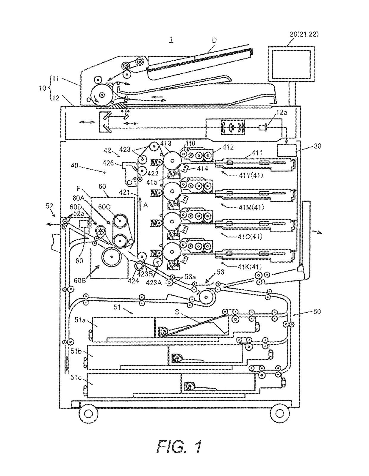
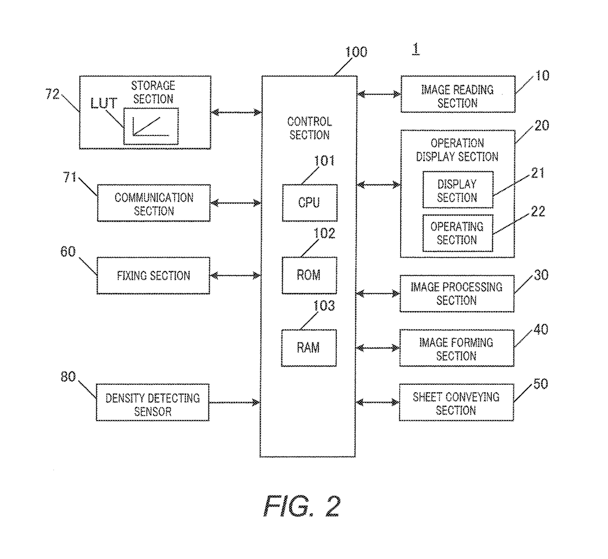
[0197]FIG. 10 schematically shows the structure of an entire image forming apparatus 1 according to Embodiment 2. FIG. 11 shows the principal components of the control system of the image forming apparatus 1 according to Embodiment 2. As can be seen from a comparison with FIG. 1, in the image forming apparatus according to Embodiment 2, density detecting sensor 80 on the downstream side of fixing section 60 is replaced with density detecting section 74 disposed in the vicinity of intermediate transfer belt 421.

[0198]Density detecting section 74 detects color information (including color elements and density) in the output image transferred onto intermediate transfer belt 421, and outputs a detection valu...

modification 1

[0261]In the above described embodiment, a secondary color image is used as a multicolor image, and the density correcting section calculates the tone of a monochrome image in accordance with the tone of the secondary color image.

[0262]In Modification 1, on the other hand, a tertiary color image in which the three colors of yellow (Y), magenta (M), and cyan (C) are mixed is used as a multicolor image, and the density correcting section calculates the tone of a secondary color image in accordance with the tone of the tertiary color image.

[0263]FIG. 19 is a diagram showing the tone of a multicolor image and the tone of a monochrome image plotted in chromatic coordinates. As shown in FIG. 19, the density correcting section calculates the tone of a secondary color image in M and C from the tone of a tertiary color image in Y, M and C and the tone of a monochrome image in Y. For example, the density correcting section corrects the data of B 80% (C 80%, M 80%) in a 3D-LUT with the calcula...

modification 2

[0265]In the above described embodiment, the tone of one of the primary colors constituting a secondary color is calculated in accordance with the tone of the secondary color and the tone of the other one of the primary colors constituting the secondary color.

[0266]In Modification 2, on the other hand, the density correcting section calculates the tone of a multicolor image obtained by combining monochrome images having the same tone. For example, the density correcting section calculates tone Gray 80% of Gray (grayscale) from a tone 80% of Y, a tone 80% of M and a tone 80% of C. With this, the tone of a multicolor image that is not included in input image data can be efficiently calculated.

[0267]The density correcting section also calculates the tone of a secondary color in accordance with the tones of the primary colors constituting the secondary color, for example, and performs density correction in accordance with the calculated tone. For example, the density correcting section ...


PUM


Abstract

An image forming system includes: a density detecting section that detects the density of a toner image formed on an image bearing member by an image forming section, the density being detected as an output image density; a hardware processor which performs; tone correction in accordance with input-output characteristics data indicating the relationship between an input image density and an output image density, the input image density being the image density of a tone component included in the input image data, the output image density being detected by the density detecting section in accordance with the tone component; determining whether there is a missing tone component in the input image data; and complementing the input-output characteristics data corresponding to a missing tone component, when it is determined that there is the missing tone component.

Description

CROSS REFERENCE TO RELATED APPLICATIONS[0001]The present invention claims priority under 35 U.S.C. §119 to Japanese Patent Application No. 2016-159908 filed Aug. 17, 2016, and Japanese Application No. 2016-171698, filed Sep. 2, 2016, the entire content of which are incorporated herein by reference.BACKGROUND1. Technological Field[0002]The present invention relates to an image forming system, an image forming apparatus, a tone correction method, a non-transitory recording medium storing a computer readable tone correction program, and an image density correction method.2. Description of the Related Art[0003]Conventionally, in a color image forming apparatus utilizing an electrophotographic process technology (such as a copier, a printer, or a facsimile machine), an intermediate transfer system using an intermediate transfer member such as an intermediate transfer belt is normally adopted. In the intermediate transfer system, toner images in the respective colors of cyan (C), magenta ...

Claims


Application Information

Patent Timeline
Patent Type & Authority Applications(United States)
IPC IPC(8): G03G15/00
CPCG03G15/0121G03G15/5029G03G15/0189G03G15/5041G03G15/5058G03G15/5062
Inventor TOYOFUKU, KATSUYAYAMANAKA, DAIKIYAMAGUCHI, TORU
Owner KONICA MINOLTA INC
Why Eureka
Try Eureka