Posts For Road Safety Barrier

a technology for road safety and posts, applied in fencing, ways, buildings, etc., can solve the problems of little connectivity/cohesion with posts, vehicle straddling, overturning of vehicles, etc., and achieve the effect of reducing the risk of post collapse or damage, and enhancing the containment/retardation capacity of vehicles

Inactive Publication Date: 2009-06-11
HILL & SMITH LTD
View PDF15 Cites 13 Cited by
  • Summary
  • Abstract
  • Description
  • Claims
  • Application Information

AI Technical Summary

Benefits of technology

[0005]It is an aim of the present invention to provide a road safety barrier which alleviates the aforementioned problems.
[0009]Embodiments of the present invention may provide an enhanced vehicle restraint capability relative to the four-wire rope fence described in EP 0 369 659 A1 particularly in cases involving larger and heavier vehicles. Further ropes may be interwoven between the posts to create a multi-rope barrier in order to achieve an increased containment capability although additional ropes to the minimum four are preferably added in pairs so the total number of ropes is even. This is so that the barrier has a more consistent resistance to vehicle penetration along its length. The ropes may be arranged in pairs at different heights on the posts or alternatively each rope may be at a different height from the others. In the latter case, the dispersion of the ropes allows the barrier to better accommodate a wide variety of vehicle types / heights and reduces the risk of rope redundancy in terms of vehicle capture.
[0012]Embodiments of the present invention are advantageous in that when a vehicle impacts the barrier, there is an enhanced vehicle containment / retardation capability and a reduced risk of post collapse or damage in the regions of the barrier up and downstream of the impact area.

Problems solved by technology

Although this safety barrier design added substantially to the containment capability over an earlier two wire rope barrier, it is now recognized that there are disadvantages associated with the parallel arrangement of the upper ropes because they have very little connectivity / cohesion with the posts.
Also because of the vertical rigidity of the posts there is a possibility of an errant vehicle straddling the safety barrier and receiving an upward thrust leading to overturning of the vehicle, if the posts fail to collapse in time.
However, a consequence of the pre-tensioning is a tendency for the interwoven ropes to grip the posts so tightly that their combined frictional grip in the direction of the line of the barrier exceeds the elastic bending strength of the posts in that direction.
This can lead to posts located some distance away from the vehicle impact zone being pulled over by the ropes towards the vehicle to the extent that they are permanently deformed.

Method used


Image

  • Posts For Road Safety Barrier
  • Posts For Road Safety Barrier
  • Posts For Road Safety Barrier

Examples


worked example

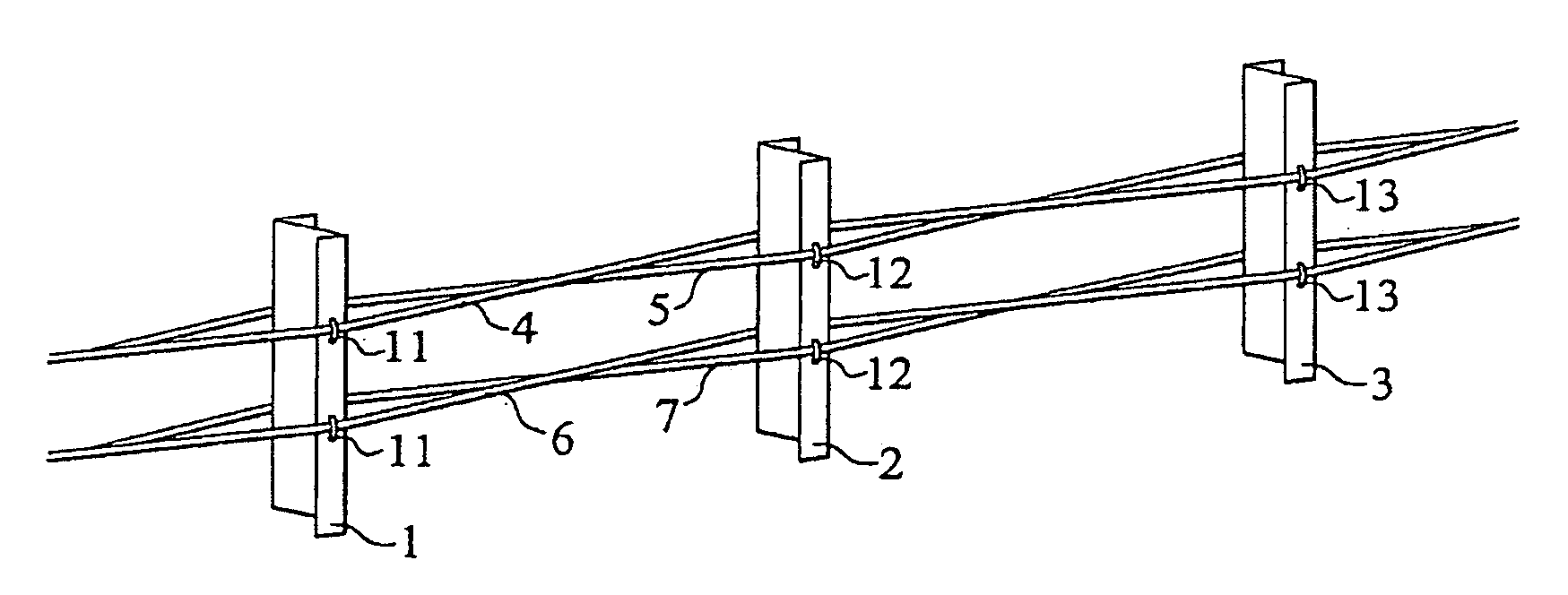
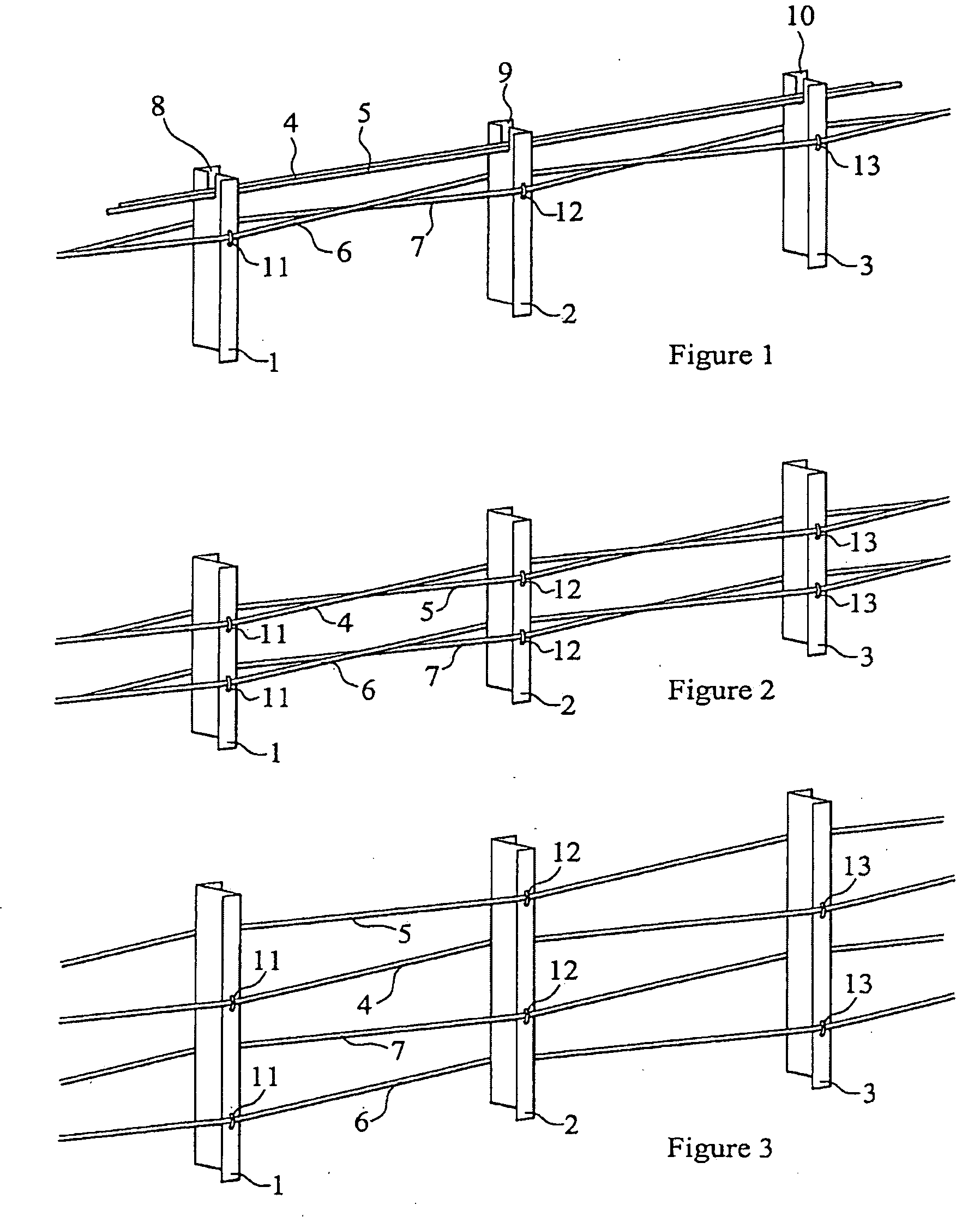
[0044]Consider the case of a 4-rope interwoven barrier in which the ropes have a mean heist above ground level of 550 mm and posts at 2.4 m spacing, each having a depth of 100 mm. The resulting angular deviation of the ropes (in plan view relative to the line of the barrier) will be 2.38 degrees. If we assume for design purposes that each rope will see a tension of 50 kN, then it can be shown that the four ropes will generate a frictional grip on a post of 3.33 kN (taking the coefficient of friction to be 0.20). The effect of this force is to create a bending moment in the post which will reach a maximum of 1832 Nm (at the base of the post) before the ropes slip. The result of this bending moment in terms of maximum bending stress will vary with the strength and stiffness of the type of post selected as illustrated in the table below:

[0045]Comparison of Maximum Bending Stresses in Z-Posts at 2.4 m Centres:

In-lineCombinedPost dimensions mmmoment ofbendingMaximum bendingD × W × Thickn...


PUM


Abstract

A road safety barrier having a plurality of ropes supported by posts rigidly mounted on or in the ground is described. Each rope is held in tension against the posts and supported in a notch or groove in a side of the posts. The ropes are released from a post and the post is not pulled from the ground when a vertical force is exerted on the rope. The ropes when weaved are tensioned against the posts and this gives rise to a combined frictional resistance to displacement of the ropes relative to each post along the length of the safety barrier. The structure of at least some of the posts and / or their mounting with respect to the ground defines a minimum bending yield strength in a direction along the length of the barrier. This minimum bending yield strength is greater than the bending moment resulting from the combined frictional resistance forces acting on the post.

Description

CROSS REFERENCE TO RELATED APPLICATIONS[0001]This application is a continuation of U.S. Ser. No. 10 / 924,240, filed Sep. 15, 2004, which claims priority to United Kingdom Patent Application No. 0321757.7, filed Sep. 17, 2003.FIELD OF THE INVENTION[0002]This invention relates to road safety barriers for use at the sides or central reservations of roads and motorways, and in particular these including a plurality of wire ropes interwoven and maintained under tension between supporting posts.SUMMARY OF THE INVENTION[0003]A known wire rope road safety barrier, described in EP 0 369 659 A1, includes two pairs of wire ropes, one pair of upper ropes supported in slots provided in a number of posts and lying generally parallel to one another, and a lower pair of ropes held in tension against and in contact with opposite side edge surfaces of posts. Each lower cable follows a sinuous path and passes to a different one of the two side surfaces of the same post. Although this safety barrier des...

Claims


Application Information

Patent Timeline
Patent Type & Authority Applications(United States)
IPC IPC(8): E01F15/02E01F15/06
CPCE01F15/06E01F15/02E01F13/00E01F15/0461E04H17/02
Inventor SHARP, GRAHAM T.BILLINGHAM, SEANWALTON, JOHN M.
Owner HILL & SMITH LTD
Why Eureka
Try Eureka