Damper

a technology of adampers and air flow, which is applied in the direction of lighting and heating apparatus, heating types, applications, etc., can solve the problems of complex mechanism operation, increased possibility of malfunction, and short life expectancy of present models, and achieves the effect of simple operation

Inactive Publication Date: 2009-06-18
MABE SA DE CV
View PDF14 Cites 0 Cited by
  • Summary
  • Abstract
  • Description
  • Claims
  • Application Information

AI Technical Summary

Benefits of technology

[0012]Therefore, a controlling mechanism that is affordable to produce, with few pieces involved, so that the failing possibilities of the controlling mechanism diminishes, and thus, has a longer life expectancy is required. Also, a simple operation is required, so that the user, and consequently the mechanism is simple to operate. A knob having an operable location for the user is also required, without affecting the refrigerator appearance. Finally, a controlling mechanism capable of having adaptability is required, that is, that it may be adapted to different refrigerator models, wherein the freezer compartment may be disposed in any of various locations, such as an upper location, a lower location or side by side to the refrigerator compartment.BRIEF DESCRIPTION OF THE PRESENT INVENTION
[0019]Therefore, an object of the present invention is to provide an affordable control mechanism to produce, wherein its construction involves few pieces, being this another object of the invention.
[0020]Another object of the invention is a control mechanism that may be operated in a simple manner by the user, and when operated, the control mechanism has simple functioning.
[0021]Yet a further object of the present invention is providing a control mechanism that as a whole, does not affect the inner appearance of the refrigerator.
[0022]Finally, another object of the invention is providing a control mechanism that has adaptability between different refrigerator model.

Problems solved by technology

Several disadvantages exist in the known controllers, such as production cost, number of pieces needed to complete the product, thus the possibility of a malfunction is greater, the operation of the mechanism is complicated, the knob location may be cumbersome, the life expectancy of present models may be short, and a lack of adaptability of the mechanism to diverse refrigerator models.
Therefore, a controlling mechanism that is affordable to produce, with few pieces involved, so that the failing possibilities of the controlling mechanism diminishes, and thus, has a longer life expectancy is required.

Method used


Image

  • Damper
  • Damper
  • Damper

Examples


Embodiment Construction

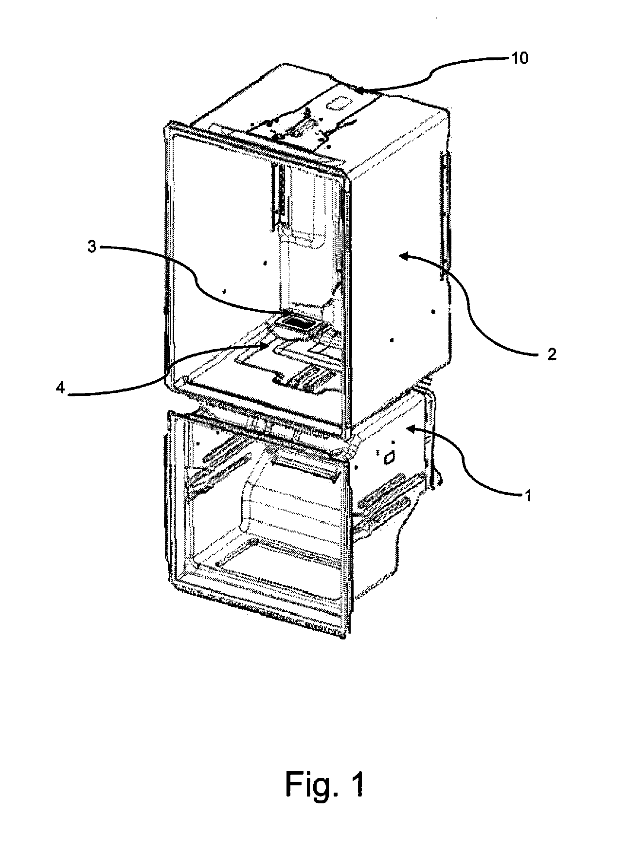
[0043]FIG. 1 shows two separate compartments. In the case illustrated by FIG. 1, the freezer compartment or cabinet (1) is found in the lower part, while the refrigerator compartment or cabinet (2) is found in the upper part. However, as will be shown, the air flow control mechanism of the present invention is capable of functioning in a refrigerator whose freezer compartment (1) is found in the upper part, while the refrigerator compartment (2) is found in the lower part, or, wherein both compartment (1, 2) are found side-by-side. In the refrigerator cabinet (2) inner part, a return section (3) may be seen, which collect the air circulating within the refrigerator cabinet (2), to send it through a plurality of return ducts (4) towards the evaporator to cool again the air, after mixing it with the collected air from the freezer compartment (1).

[0044]In the upper part of the refrigerator cabinet (2) an air flow controlling mechanism (10) may be found.

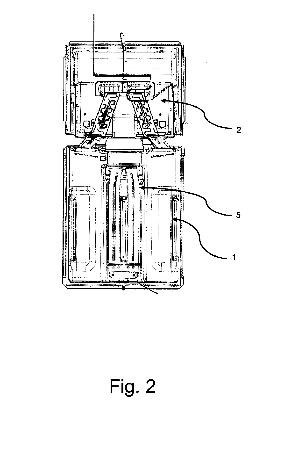
[0045]FIG. 2 shows the back part ...


PUM


Abstract

An air flow control mechanism for a refrigerator or freezer is disclosed comprising at least one knob to regulate by its adjustment, air flow within a compartment, the knob including at least one end, and wherein said knob is configured to rotate, a cam including a base, a groove and a receiving end, wherein the cam base includes the groove, wherein the groove is a semi-circular shape and is un-centered with regards to the cam base and wherein said receiving end receives said knob end, a crank having a first end a second end, wherein said first end is inserted in the semi-circular groove of said cam base and is configured to run said groove when the user adjusts the knob, a rod having a front end and a back end, wherein said front end is connected to said crank second end, and an obturator connected with said rod back end. Said cam base has the same rotation degree than the knob and wherein the rotational movement of said knob is transformed and transmitted to the crank and consequently the rod.

Description

FIELD OF THE INVENTION[0001]The present invention refers to mechanisms and methods for controlling air flow in refrigerators, and specifically to mechanisms and methods for controlling and regulating cold air to be provided to the inner refrigerator compartment.PRIOR ART DESCRIPTION[0002]A typical refrigerator construction comprises two compartments: a freezer compartment and a refrigerator or fresh food compartment. To provide cold air from the air chamber a fan is used, sucking air coming from the evaporator and supplying kinetic energy to the air, so that said air may reach both compartments by means of ducts. The air is divided and distributed by means of a liner fixed to the evaporator housing and placed in front of the ventilator. That is, a portion of cold air generated in the evaporator is guided to the freezer compartment by a fan or any other means that force the air flow through the ducts. The air guided to the freezer circulates in the freezer chamber, reaching temperatu...

Claims


Application Information

Patent Timeline
Patent Type & Authority Applications(United States)
IPC IPC(8): F24F11/04
CPCF25D17/045
Inventor CRUZ, MARCO ANTONIO SOLISRAZO, VICTOR HUGO MIRANDA
Owner MABE SA DE CV
Why Eureka
Try Eureka