Rheostatic safety braking device having a bipolar resistive assembly with permanent magnet motor

a technology of permanent magnet motor and rheostatic safety braking, which is applied in the direction of motor/generator/converter stopper, dynamo-electric converter control, instruments, etc., can solve the problems of inability to adjust, the probability of failure must be extremely low, and the inability to be secur

Active Publication Date: 2009-09-10
ALSTOM TRANSPORT TECH SAS
View PDF7 Cites 13 Cited by
  • Summary
  • Abstract
  • Description
  • Claims
  • Application Information

AI Technical Summary

Benefits of technology

[0009]This invention proposes an electric safety brake which is based on the fact that an electric motor with permanent m

Problems solved by technology

However, it is not secure in the sense that it involves a large number of electric, electronic, mechanical, pneumatic or hydraulic components which may malfunction and therefore bring about a different braking force from that desired, or even, with the new traction chains having traction/static braking commutation, a traction force.
This brake cannot be adjusted but is reliable, that is to say, its probabi

Method used


Image

  • Rheostatic safety braking device having a bipolar resistive assembly with permanent magnet motor
  • Rheostatic safety braking device having a bipolar resistive assembly with permanent magnet motor
  • Rheostatic safety braking device having a bipolar resistive assembly with permanent magnet motor

Examples


first embodiment

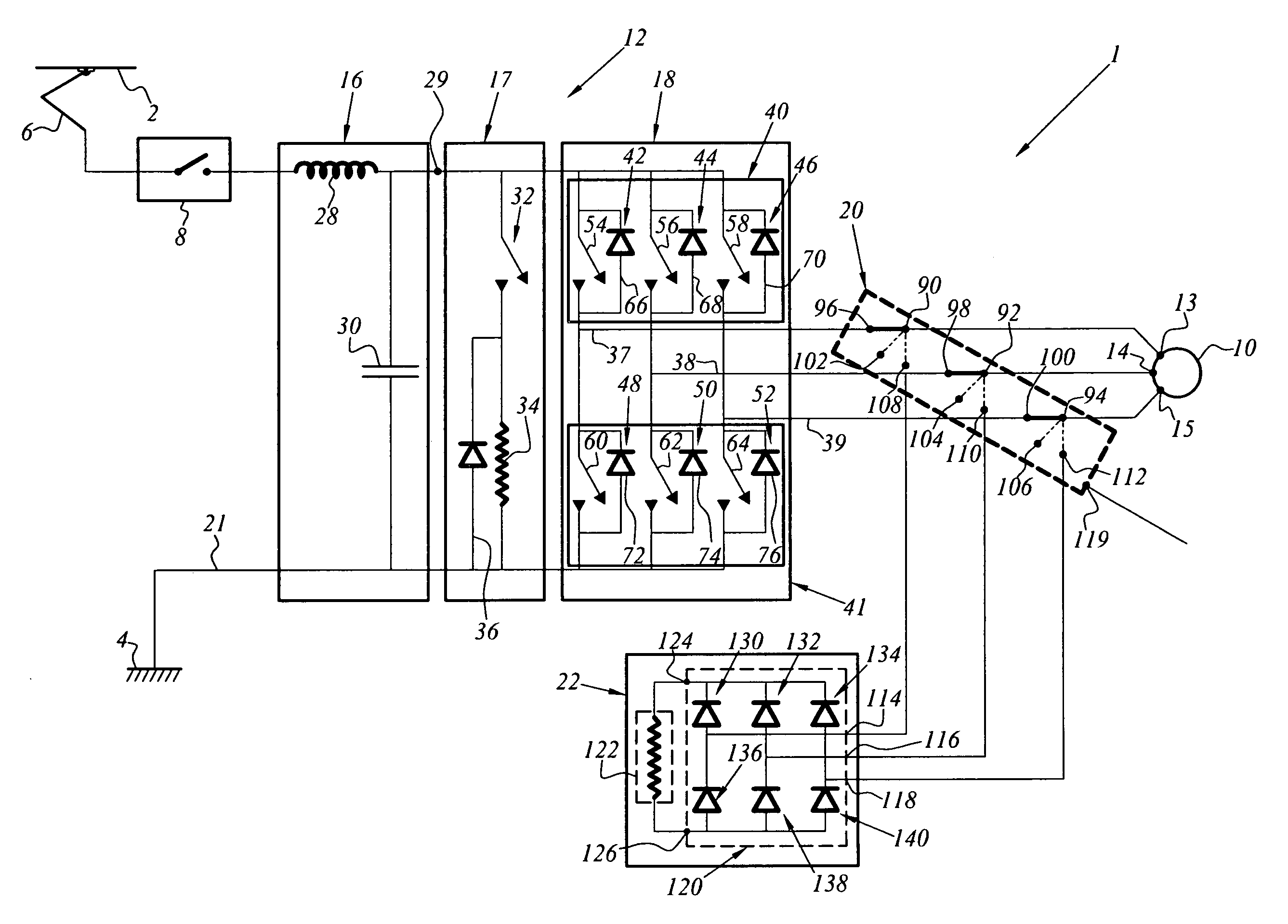
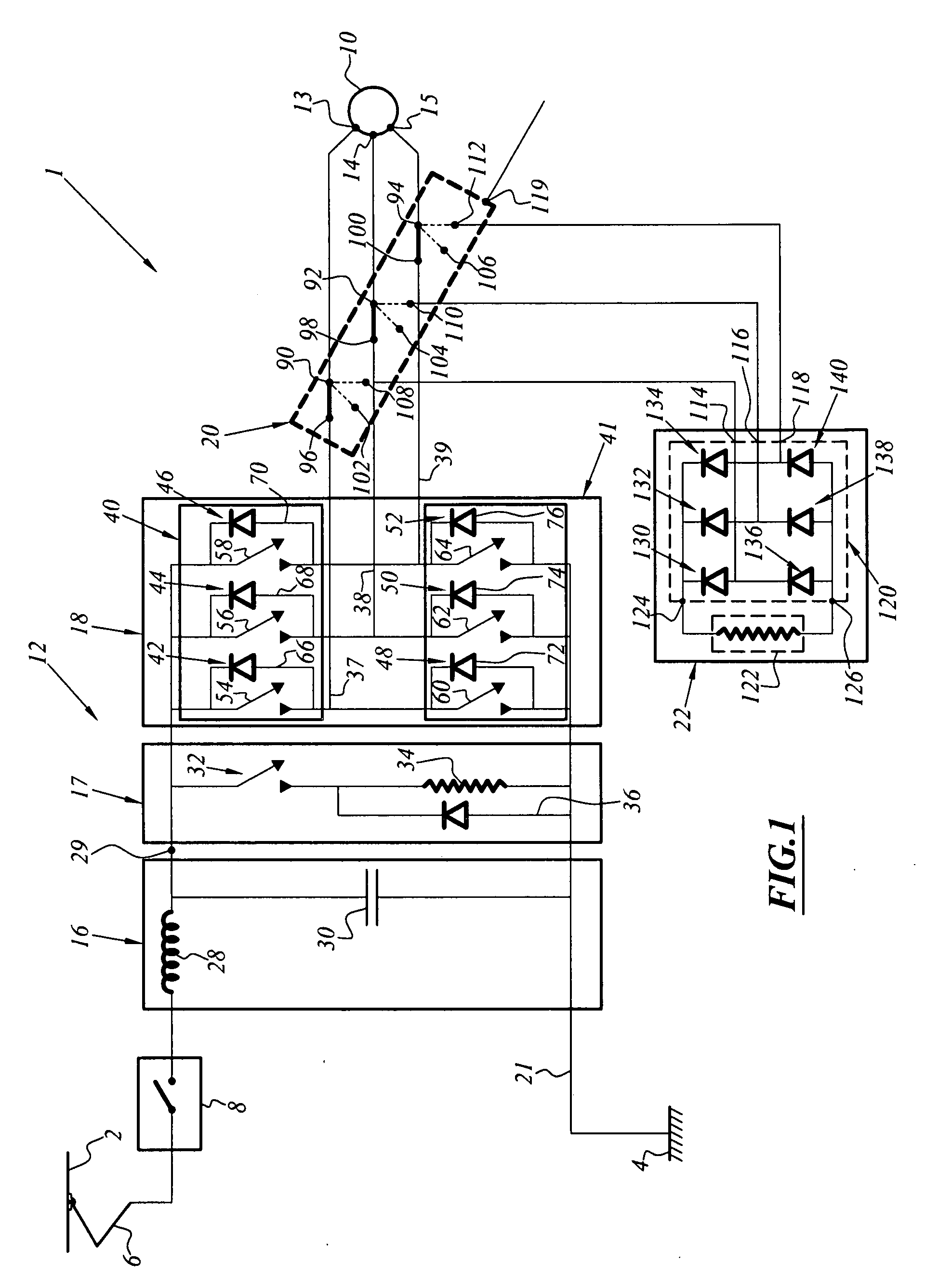
[0058]Since the space occupied by the diode bridge rectifier is small compared with that associated with a resistor, and the structure formed by the first embodiment can also be used for any number of motor stator phases by adding diodes to the bridge, using a single load resistor advantageously allows space to be saved.

second embodiment

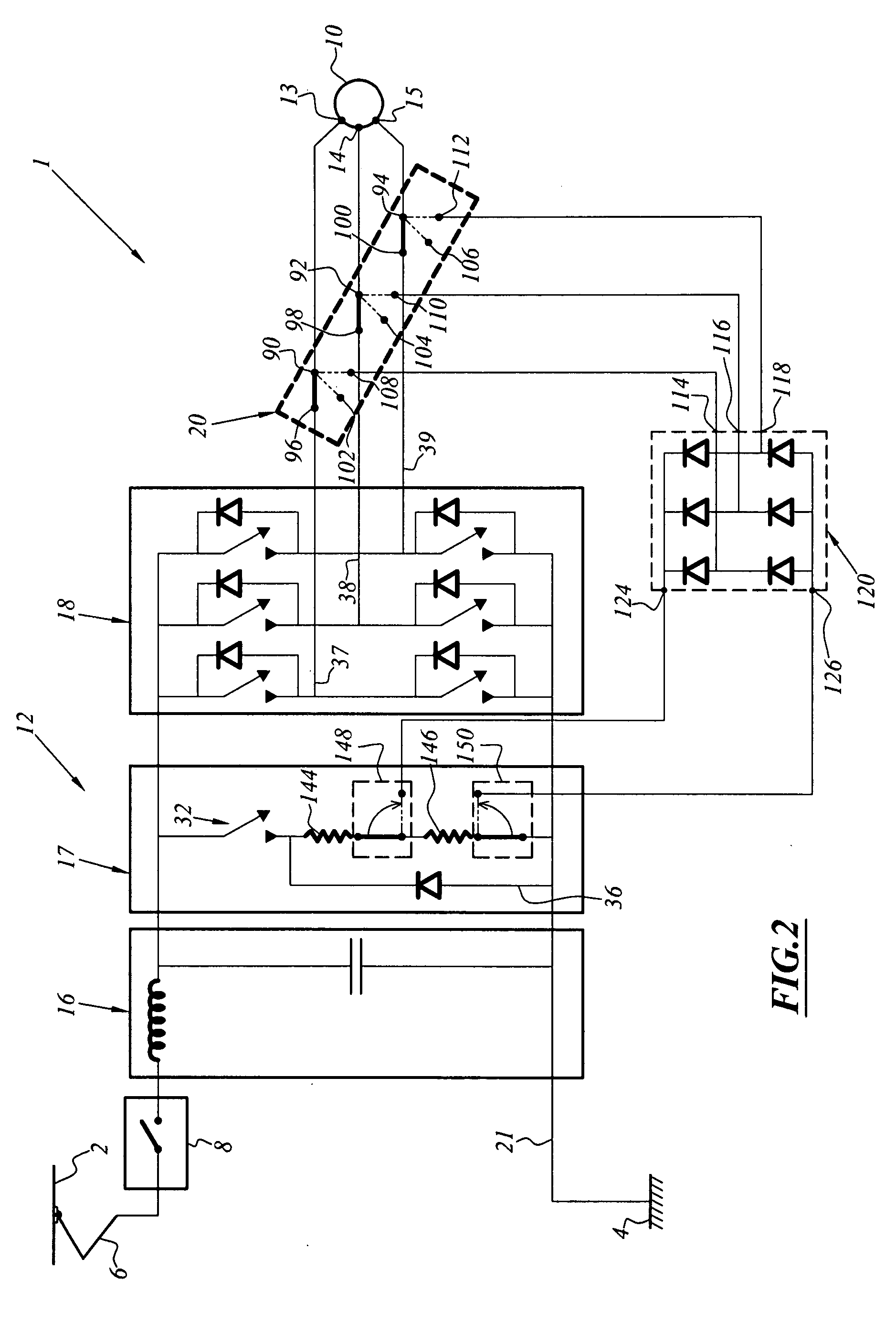
[0059]FIG. 2 illustrates the electric safety brake which is integrated in the electric traction chain.

[0060]The traction chain 1 is similar to that described in FIG. 1 and differs in that the rheostatic brake resistor 34 of the chopper 17 of FIG. 1 is replaced by an assembly of two resistors 144, 146 in series, in that the resistor which is located closest to the earth return line 21, in this instance the resistor 146, acts as a load resistor for the electric safety brake, and that there is arranged at one side and the other of the resistor 146, two electromechanical commutators 148, 150, one of which, 148, allows a terminal of the resistor 146 to be connected, either to the resistor 144 or to the output 124 of the diode bridge 120 of the electric safety brake and the other, 150, allows the other terminal of the resistor 146 to be connected either to the output 126 of the diode bridge 120 of the electric safety brake or to the earth return line 21 of the chopper.

[0061]That is to say...


PUM


Abstract

This device is an electric safety brake which is intended for an electric traction vehicle, in particular a rail vehicle comprising: a rotating electromechanical machine (10) having permanent magnets having at least one coil with electric terminals (13, 14, 15), a resistive braking torque production device (22), an electromechanical commutator (20) which is capable of reliably connecting the electric terminals (13, 14, 15) of the machine (10) to the braking torque production device (22).
It is characterised in that the braking torque production device (22) comprises, on the one hand, a bipolar assembly (122) of at least one dissipative resistor, the assembly having two single connection terminals and forming a common terminal bipolar electric output load for all the terminals (13, 14, 15) of the mechanism and, on the other hand, means (120) for converting the currents from all the terminals (13, 14, 15) into a single current which is supplied to the two single terminals of the assembly of at least one dissipative resistor, the conversion means (120) having no active power switches.

Description

[0001]This claims the benefit of FR 07 57338 filed on Sep. 4, 2008 and hereby incorporated by reference herein.[0002]The invention relates to an electric safety braking device which is intended for a vehicle which is electrically driven, for example, a rail vehicle.[0003]A safety braking system ensures the desired braking force is produced in an extremely reliable manner.BACKGROUND OF THE INVENTION[0004]In the field of rail transport, there are principally two types of braking operation: service braking and emergency braking.[0005]The service braking operation is the one which is most commonly used during operation. It can be adjusted between a minimum force value close to 0 and a maximum force value. It can be broken down itself into a plurality of modes, depending on the trains: purely electric brake, purely mechanical brake or combined electric and mechanical brake. It carries out all the “normal” stopping and deceleration operations of the train, and the braking operations for h...

Claims


Application Information

Patent Timeline
IPC IPC(8): H02P3/22
CPCB60L7/003B60L2200/26B60L7/06B61H11/02
Inventor JOBARD, THIERRYBONIN, ERIC
Owner ALSTOM TRANSPORT TECH SAS
Why Eureka
Try Eureka