Camera System to detect, monitor and report low visibility

a camera system and low-visibility technology, applied in the field of intelligent camera systems, can solve the problems of reducing the speed of the camera system, affecting the detection effect, and causing the loss of lives of thousands, so as to reduce the speed and reduce the visibility of images

Inactive Publication Date: 2009-10-15
GANESHAN RAM
View PDF4 Cites 29 Cited by
  • Summary
  • Abstract
  • Description
  • Claims
  • Application Information

AI Technical Summary

Benefits of technology

[0009]The present invention relates to a vision camera system to detect low visibility conditions. A special vision camera with image processing software is used to view a fixed object (e.g., lights) at a distance continuously. The software in the camera and the system is programmed to process the different parameters of the images of the object. The parameters could be e.g., the in

Problems solved by technology

Thousands of lives are lost, thousands are seriously injured and billions of dollars are paid out in collateral damages every year in the USA due to automobile accidents on the roads due to low visibility caused by fog or snow storm, heavy rains, smoke and dust storms.
To detect the occurrence of fog ov

Method used


Image

  • Camera System to detect, monitor and report low visibility
  • Camera System to detect, monitor and report low visibility
  • Camera System to detect, monitor and report low visibility

Examples


Embodiment Construction

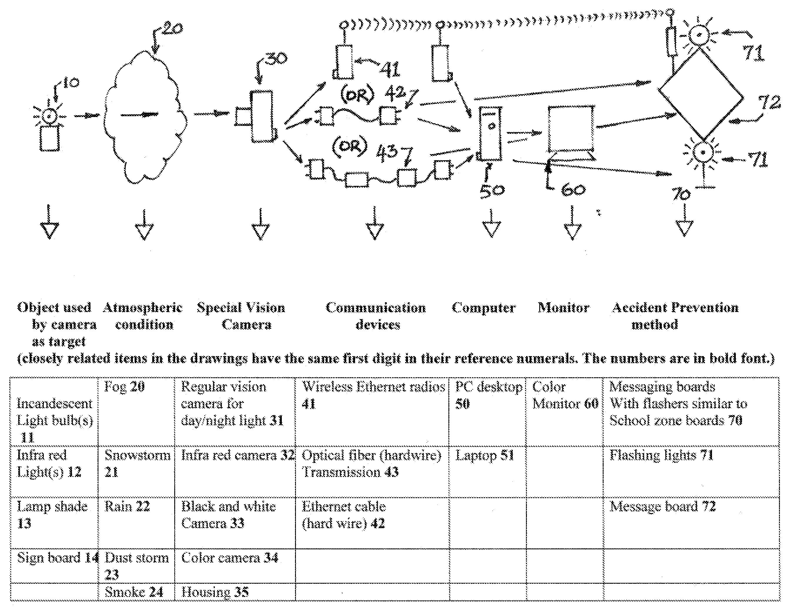
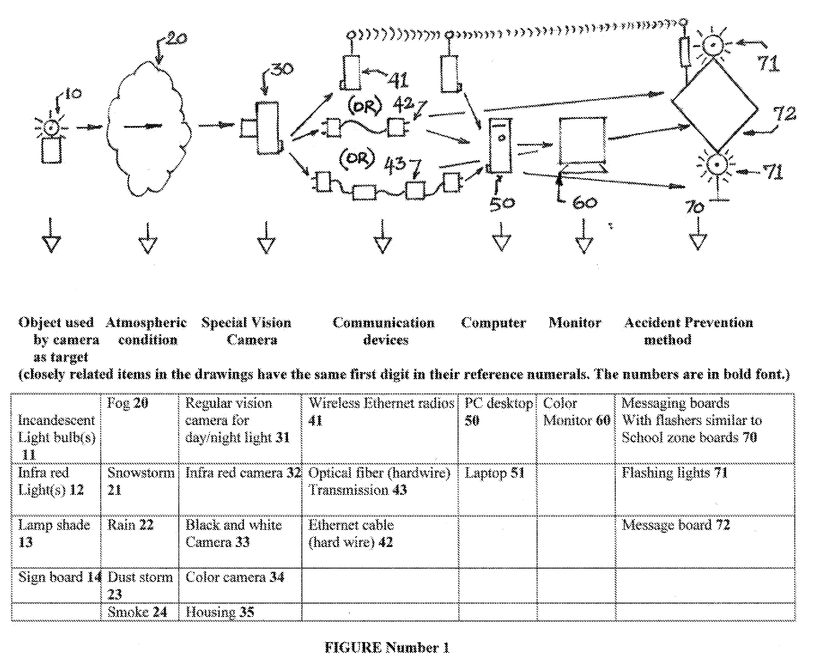
1. Camera, Lights, Wireless Ethernet Radios (WER), Flashing Lights on Emergency Messaging Board (EMB)

[0012]A preferred embodiment of the present invention provides a method for monitoring the low visibility on the road by using a vision camera, a light source, a set of wireless Ethernet radios and an Emergency Messaging Signboard with flashing lights.
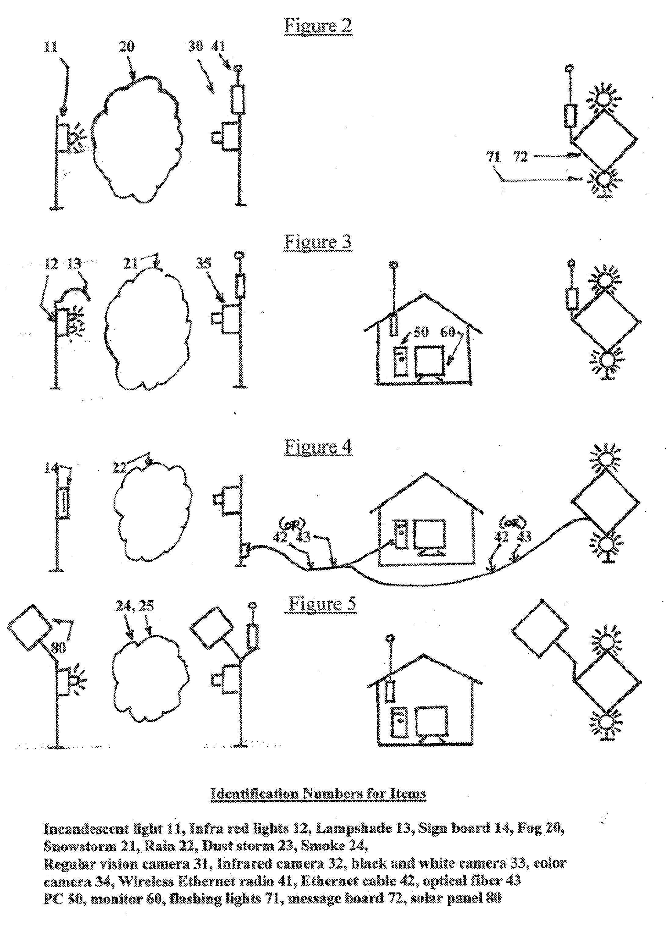
[0013]See FIG. 2.

[0014]The camera is installed in a weatherproof and climate controlled housing, mounted on a pole. The centerline of lens will be at about 15 feet height. The housing will also have a wireless Ethernet radio transmitter in it connected to the camera. It will transmit images and digital inspection results.

[0015]A light or a set of lights (in this example, four in number) is mounted on a panel (for this example, on the 4 corners of a square, 2 feet×2 feet). The panel is installed on a pole so that the center of the square is at the same elevation as the lens and the camera is viewing the 4 lights. The lights could be of i...


PUM


Abstract

The invention comprises of a method and a system to detect, monitor and report hazardous conditions of low visibility on roadways and waterways occurring due to fog or snow or rain or dust or smoke. A special vision camera installed on a post on the road or the waterway continuously views a set of lights installed on another post at a distance a few hundred feet away. The system software is used to set up a frame around the captured image. A value is assigned to the intensity of the light in the image under normal conditions of visibility. A tolerance range is set up around that assigned value. If the intensity value goes out of the set tolerance range due to low visibility conditions in the space between the camera and the target light(s), the software initiates an alarm state. This digital output is translated into an appropriate emergency message to be flashed on the electronic signboards on the roads or waterways.

Description

CROSS REFERENCE TO RELATED APPLICATION[0001]U.S. Pat. No. 6,278,374 B1[0002]USPTO's Number for the provisional application of this patent: 60 / 762,310[0003]Provisional Application filing date: Jan. 27, 2006FEDERALLY SPONSORED RESEARCH[0004]Not applicableSEQUENCE LISTING OF PROGRAM[0005]not applicableBACKGROUND OF THE INVENTION[0006]Thousands of lives are lost, thousands are seriously injured and billions of dollars are paid out in collateral damages every year in the USA due to automobile accidents on the roads due to low visibility caused by fog or snow storm, heavy rains, smoke and dust storms.[0007]The invention describes an intelligent camera system that will monitor selected zones of the roads continuously for low visibility conditions and alert the motorists of the hazardous conditions well in advance.Comparison of Invented Technology With Available Technology:[0008]Presently available other technology: The equipment available presently in the market place for measuring low vis...

Claims


Application Information

Patent Timeline
IPC IPC(8): H04N7/18G08G1/09
CPCG08G1/0967G08G1/04
Inventor GANESHAN, RAM
Owner GANESHAN RAM
Why Eureka
Try Eureka