

FM receiver
a receiver and frequency modulation technology, applied in the direction of transmission, electrical equipment, etc., can solve the problem that the audio signal reproduced by the receiver may be deteriorated
- Summary
- Abstract
- Description
- Claims
- Application Information
AI Technical Summary
Problems solved by technology
Method used
Image



Examples
first embodiment
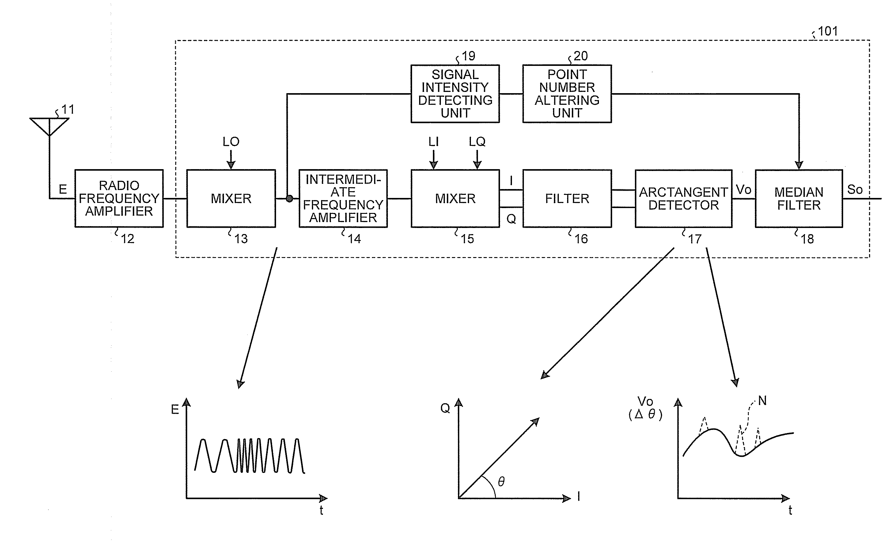
[0021]FIG. 1 is a block diagram of an FM receiver according to a first embodiment of the present invention.
[0022]In FIG. 1, the FM receiver includes a receiving antenna 11 that receives a radio wave transmitted in space, a radio frequency amplifier 12 that amplifies an FM received signal E received by the receiving antenna 11, a mixer 13 that multiplies the FM received signal E amplified by the radio frequency amplifier 12 by a local oscillate signal LO, thereby downconverting the FM received signal E, an intermediate frequency amplifier 14 that amplifies the FM received signal E downconverted by the mixer 13, a mixer 15 that multiplies the FM received signal E amplified by the intermediate frequency amplifier 14 by local oscillate signals LI and LQ that are perpendicular to each other, thereby converting the FM received signal E into an in-phase component I and a quadrature component Q, and a filter 16 that removes an unnecessary high-frequency component from the output from the mi...
second embodiment
[0052]FIG. 7 is a block diagram of an FM receiver according to a second embodiment of the present invention.
[0053]In FIG. 7, the FM receiver includes a noise intensity detecting unit 21 and a point number altering unit 22 in place of the signal intensity detecting unit 19 and the point number altering unit 20 shown in FIG. 1.
[0054]The mixers 13 and 15, the intermediate frequency amplifier 14, the filter 16, the arctangent detector 17, the median filter 18, the noise intensity detecting unit 21, and the point number altering unit 22 may be formed on an IC chip 102. The radio frequency amplifier 12 may be modularized separately of the IC chip 102.
[0055]The noise intensity detecting unit 21 can detect the intensity of the noise N of the demodulated signal Vo output from the arctangent detector 17 based on the difference between the input value and the output value of the median filter 18. The point number altering unit 22 can alter the point number in the median filter 18 based on the ...
third embodiment
[0062]FIG. 8 is a block diagram of an FM demodulator that is applied to an FM receiver according to a third embodiment of the present invention.
[0063]In FIG. 8, the FM demodulator includes the arctangent detector 17, the median filter 18, a subtractor 31, a determining circuit 32, and a selector 33. The arctangent detector 17 and the median filter 18 each have the identical configuration as that shown in FIG. 1. The subtractor 31 can detect an intensity Vp of the noise N of the demodulated signal Vo generated by the arctangent detector 17 by calculating the difference between the input value and the output value of the median filter 18.
[0064]The determining circuit 32 can determine whether the intensity Vp of the noise N of the demodulated signal Vo detected by the subtractor 31 exceeds a threshold value Vth. The intensity Vp of the noise N that is compared with the threshold value Vth by the determining circuit 32 may be the peak intensity of the noise N for the unit time, or may b...
PUM
 Abstract
Description
Claims
Application Information