Mask and flow generator system

a generator system and mask technology, applied in the field of respiratory therapies, can solve the problems of destroying the quality of sleep of patients, putting extra strain on patients' hearts, significant health problems, etc., and achieve the effects of reducing the functional dead space of the mask, reducing the functional dead space, and minimizing the internal volume of the mask

Inactive Publication Date: 2009-12-31
RESMED LTD
View PDF50 Cites 88 Cited by
  • Summary
  • Abstract
  • Description
  • Claims
  • Application Information

AI Technical Summary

Benefits of technology

[0036]An even further advantage of the present invention associated with the removal of the air tubing is a reduction in the functional dead space of the mask. Functional dead space is defined as the volume of exhaled air that is trapped within the system and that the patient subsequently re-breathes. It is desirable that functional dead space is kept within a safe range, or in the most extreme cases this could lead to the eventual patient suffocation. Current techniques to reduce functional dead space involve minimizing internal volume of the mask to minimize the amount of CO2 that is re-breathed and maximising the vent size and thus air flow through the mask to flush out the trapped CO2. Part of the CO2 that is re-breathed by the patient comes from the exhaled air that is breathed back into the tube. By removing the tube this reduces the physical volume that is available to trap CO2 and hence reduces functional dead space. This has implications for mask design. The first implication is that the internal volume of the mask can be made larger to increase the range of fit for each mask. The second implication is that this could lead to reduced flow requirements. If less CO2 is trapped in the mask, then the required flow rate to remove this CO2 is less. Reducing the flow rate will lead to a reduction in noise created as air rushes through the vents, reduce the power requirements of the pump, and increase patient comfort.

Problems solved by technology

Most OSA suffers do not remember these arousals however each arousal places extra strain on a patient's heart and destroys the quality of their sleep.
Studies have shown it can lead to significant health problems if left untreated.

Method used


Image

  • Mask and flow generator system
  • Mask and flow generator system
  • Mask and flow generator system

Examples


Embodiment Construction

[0069]4. System Design

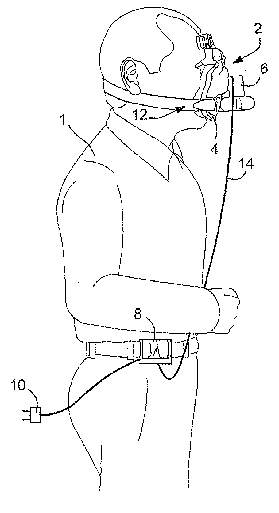
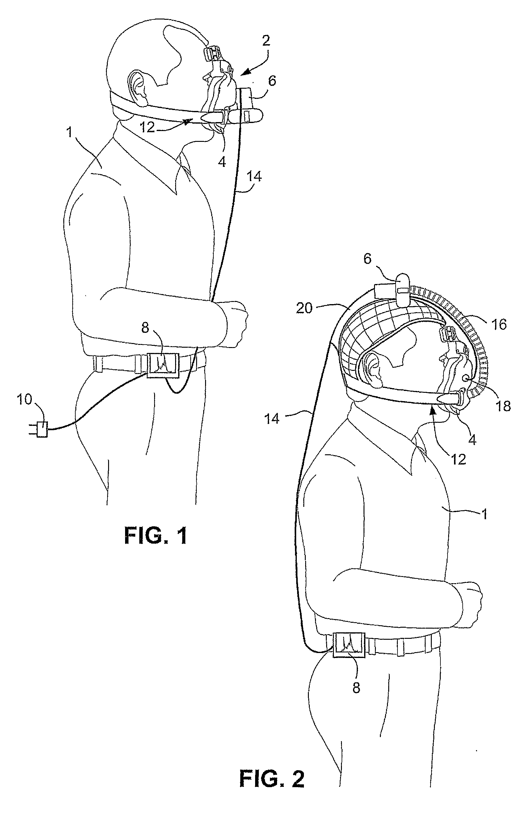
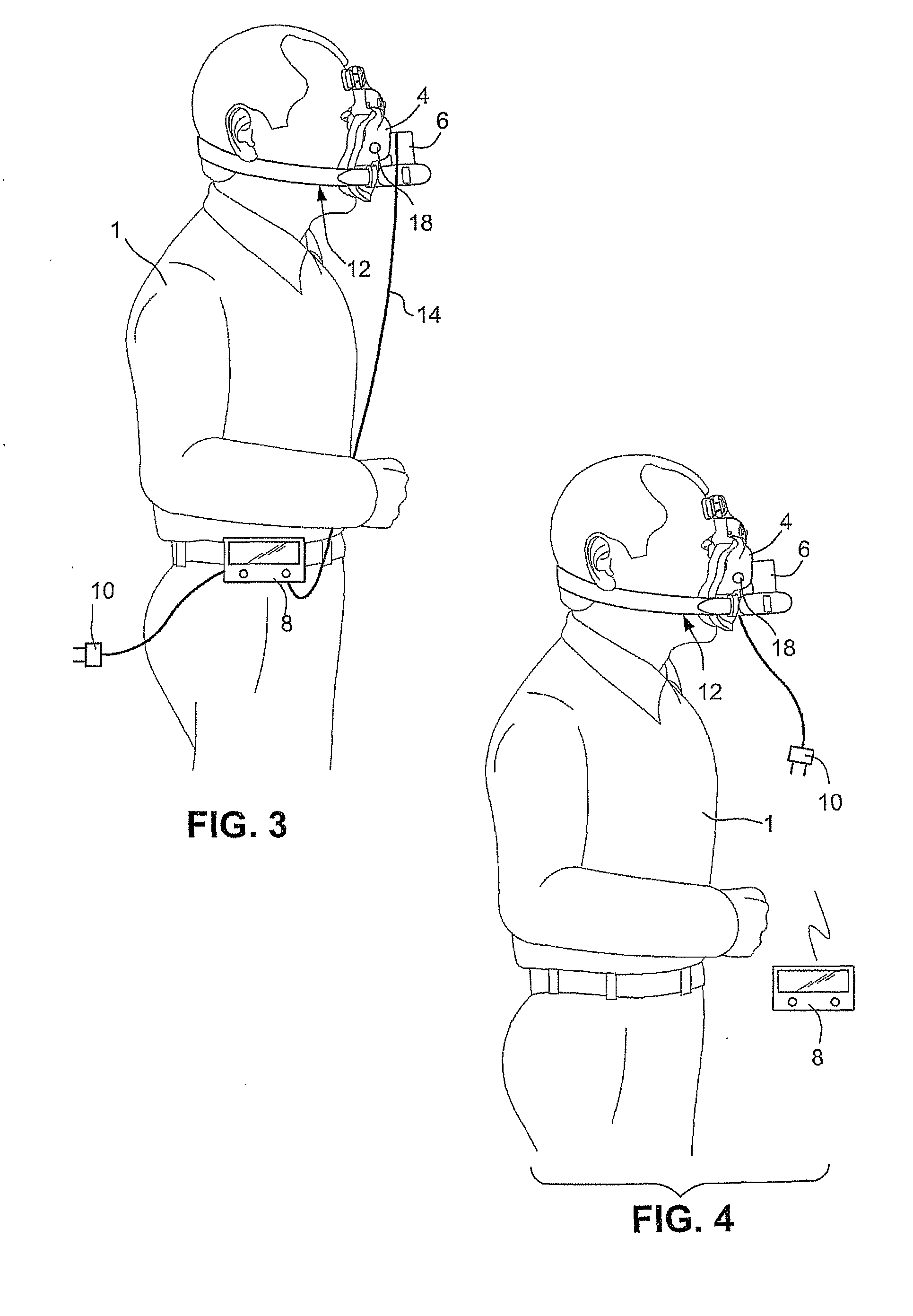
[0070]Referring to FIG. 1, a NIPPV system according to the present invention can generally be divided into two components. The first component is the user interface 8. The user interface 8 houses electrical components and allows the user 1 to control the system. The second component is the patient interface 2. The patient interface 2 is configured to house a flow generator 6, e.g., a pump, configured to generate a pressurised airflow in a mask 4 and deliver the pressurized flow into the user's airways. It should be appreciated that the mask 4 may be a nasal mask or a full face mask.

[0071]A power supply connector 10 may be provided to the user interface 8 to provide power to the user interface 8. The power supply connector 10 may also be configured to charge a rechargeable battery of the user interface 8.

[0072]The patient interface 2 may also include a headgear 12 configured to secure the mask 4 to the patient's face so that the mask 4 forms a substantially leak...


PUM


Abstract

A system for delivering a pressurized flow of breathable gas to a patient includes a patient interface configured to contact the patient's head. The patient interface includes a frame, a cushion supported by the frame and configured to sealingly connect the patient interface to the patient's face and form a chamber between the frame and the wearer's face, and an inlet port in the frame to receive the pressurized flow of breathable gas. A flow generator is configured to generate the pressurized flow and is capable of creating a pressure of about 2-40 cm H20 in the chamber. A flow generator housing is provided to house the flow generator. The flow generator housing is mounted on the patient interface and configured to reduce the transmission of vibration and/or noise generated by the flow generator to the patient interface.

Description

[0001]This application claims priority to Australian Provisional Applications 2006904900 and 2006905967, filed Sep. 7, 2006 and Oct. 27, 2006, respectively, the entire contents of which are incorporated herein by reference. WO 2005 / 028009 is also incorporated herein by reference in its entirety.BACKGROUND OF THE INVENTION[0002]1. Field of the Invention[0003]The present invention relates to respiratory therapies, including but not limited to, Continuous Positive Airway Pressure (CPAP), bi-level and ventilation therapies. The present invention also relates to a mask and flow generator system that delivers a flow of pressurized breathable gas, e.g. air, to a patient for treatment of various breathing disorders. The present invention further relates to a system in which the flow generator is incorporated with the mask or a headgear that supports the mask.[0004]2. Description of the Related Art[0005]Obstructive Sleep Apnea (OSA) is a sleep breathing disorder (SBD). For those who have OSA...

Claims


Application Information

Patent Timeline
Patent Type & Authority Applications(United States)
IPC IPC(8): A61M16/06A61M16/00
CPCA61M16/06A61M16/0683A61M16/0066A61M2016/0027A61M2016/0033A61M2205/3368A61M16/0638A61M2205/3592A61M2205/42A61M2205/502A61M2205/8206A61M2209/088A61M2205/3569A61M2205/0238A61M16/0069A61M16/0858
Inventor DOHERTY, RENEE FRANCESKWOK, PHILIP RODNEY
Owner RESMED LTD
Why Eureka
Try Eureka