Two-For-One Twisting Spindle Having a Pneumatically Actuated Threading Device

a technology of pneumatic action and twisting spindle, which is applied in the direction of piercing arrangement, textiles and papermaking, yarn, etc., can solve the problems of unsatisfactory efficiency of the known design, high production cost of the known embodiment, and high cost of spindle shaft manufacturing, etc., to achieve low cost, simple production, and economic production

Inactive Publication Date: 2010-01-28
SAURER TECH GMBH & CO KG
View PDF4 Cites 15 Cited by
  • Summary
  • Abstract
  • Description
  • Claims
  • Application Information

AI Technical Summary

Benefits of technology

[0015]A connection element, which is comprised of two components rigidly connected to one another, which are mirror-inverted with respect to one another, is simple to produce and less expensive in comparison to a connection element produced in one piece.
[0016]If the connection element is comprised of glass fiber-reinforced plastics material, it can be produced economically, has only a low weight and is durable.
[0017]A sealing ring between the connection element and the spindle shaft and between the connection element and the injector element, in each case, represents an economical and functionally reliable seal of the compressed air feed.
[0018]The configuration of the connection element as a separate component allows easy production and adaptation of the air channel to the flow requirements. This contributes to it being possible to economically produce a two-for-one twisting spindle according to the invention. The economy during the threading process is improved by low compressed air consumption, which is possible because of the increased injector effect.

Problems solved by technology

The production costs of these known embodiments are high.
In particular, the manufacturing of the channels in the spindle shaft is expensive.
The efficiency of the known designs is unsatisfactorily low.
The configuration of the air guide in the known embodiments to the thread channel limits the efficiency.
The swirlings occurring at the deflection point reduce the efficiency of the injector element as the compressed air must be fed at a higher pressure to compensate this effect.

Method used


Image

  • Two-For-One Twisting Spindle Having a Pneumatically Actuated Threading Device
  • Two-For-One Twisting Spindle Having a Pneumatically Actuated Threading Device
  • Two-For-One Twisting Spindle Having a Pneumatically Actuated Threading Device

Examples


Embodiment Construction

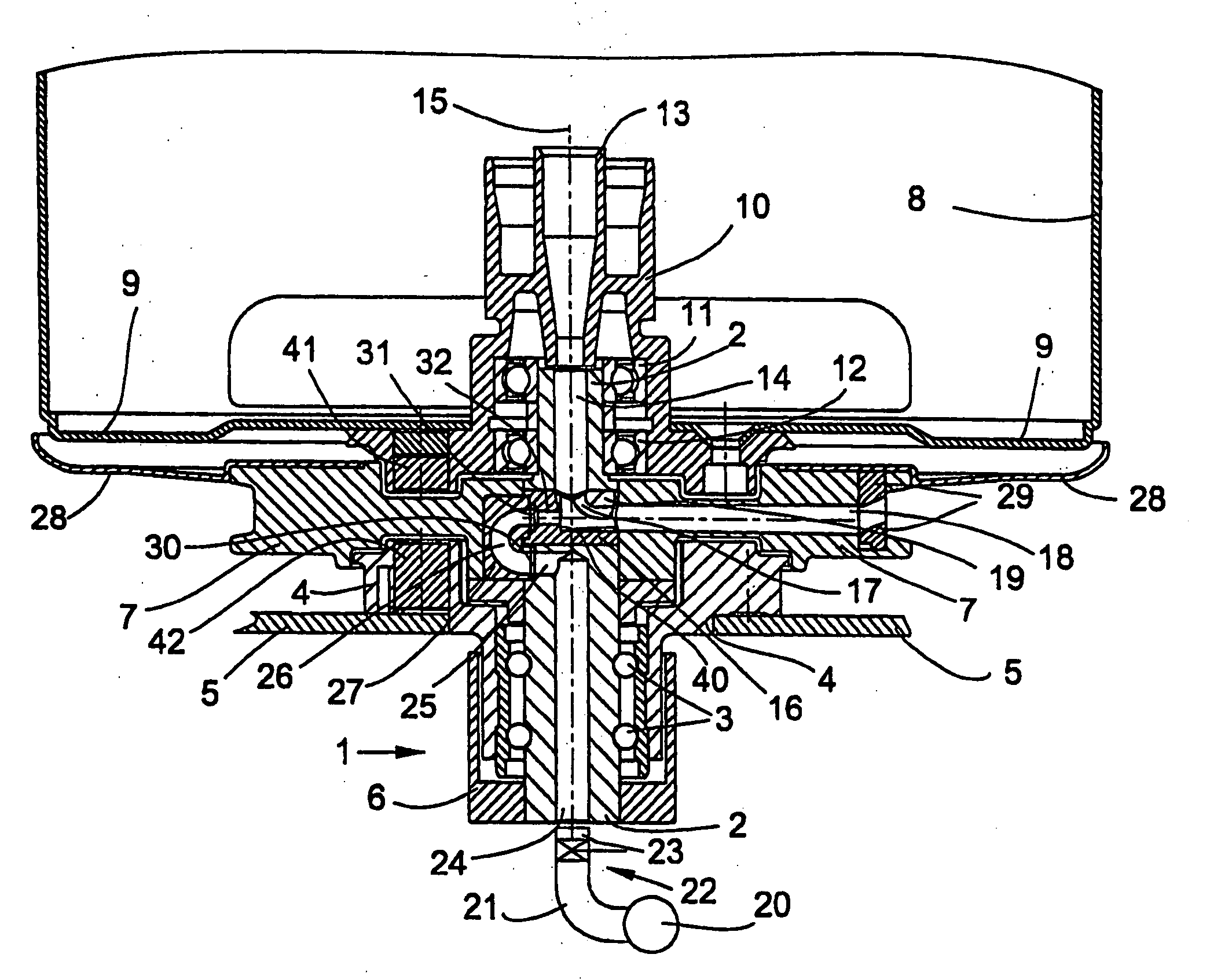
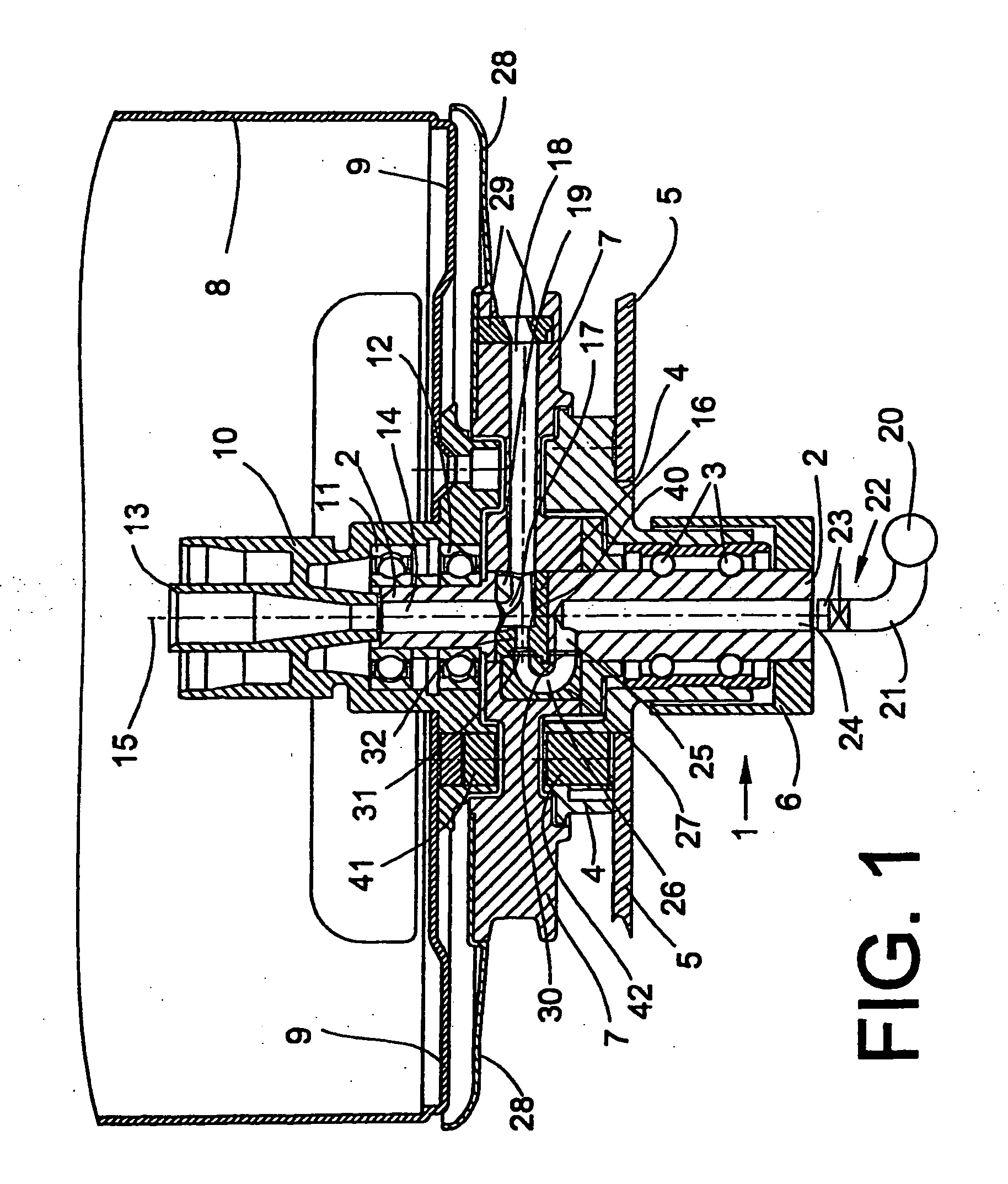
[0023]FIG. 1 shows a two-for-one twisting spindle with a spindle bearing arrangement 1. The spindle shaft 2 configured in one piece is rotatably mounted in the bearing housing 4 by means of a ball bearing arrangement 3. The bearing housing 4 is fastened to the spindle rail 5. The spindle shaft 2 carries a drive wharve 6, a thread guide ring 7 and a bobbin pot 8 with a bobbin carrier base 9 and hollow hub 10. The hollow hub 10 is mounted by means of ball bearings 11, 12 on the spindle shaft 2 and has a coaxially thread tube 13. The thread tube 13 opens into the upper hollow axle 14 of the spindle shaft 2. The spindle shaft 2 can be rotated about the perpendicularly extending rotational axis 15. A recess passing through the spindle shaft 2, with an oval cross section, extends transversely to the rotational axis 15. An injector element 16 made of plastics material is inserted into the recess. It can be produced as an injection moulded part, economically and so as to fit precisely, corr...


PUM

PropertyMeasurementUnit
diameteraaaaaaaaaa
diameteraaaaaaaaaa
radiusaaaaaaaaaa

Abstract

Two-for-one twisting spindle having a pneumatically actuated threading device, with a spindle shaft rotatable about a vertical axis partially configured as a hollow shaft with a lower feed bore extending coaxially to the rotational axis, and with an injector element opening into a thread guide channel of a thread guide ring temporarily connectable during threading to a compressed air source. Part of the compressed air feed to the injector element is formed by the feed bore. The compressed air feed comprises a connection element (27) with a curved air channel (26), which connects the feed bore (24) to the injector element (16). The connection element (27) is configured as a separate component and the air channel (26) is adapted to the flow requirements.

Description

CROSS-REFERENCES TO RELATED APPLICATIONS[0001]This application claims the benefit of German patent application 10 2006 029 055.0, filed Jun. 24, 2006, herein incorporated by reference.BACKGROUND OF THE INVENTION[0002]The invention relates to a two-for-one twisting spindle having a pneumatically actuated threading device.[0003]In two-for-one twisting spindles, the thread is generally drawn off upwardly from the stationary supply bobbin, introduced into the upper end of a thread inlet tube, deflected downwardly and guided by a thread brake into the spindle rotor or into the spindle shaft, which it leaves again in the radial direction through a thread guide channel.[0004]After leaving the thread guide channel, the thread is guided upwardly and, during the twisting, forms a balloon rotating about the supply bobbin. The thread then runs through a thread guide and is wound, twisted, onto a take-up bobbin.[0005]On modern two-for-one twisting machines, the threading of the thread takes plac...

Claims


Application Information

Patent Timeline
Patent Type & Authority Applications(United States)
IPC IPC(8): D01H9/00
CPCD01H7/88
Inventor FINK, HEINZTETZLAFF, GEORGSINGER, SERGEI
Owner SAURER TECH GMBH & CO KG
Why Eureka
Try Eureka