Buffer management method and apparatus thereof

Inactive Publication Date: 2010-03-11
MEDIATEK INC
View PDF2 Cites 4 Cited by
  • Summary
  • Abstract
  • Description
  • Claims
  • Application Information

AI Technical Summary

Benefits of technology

[0037]In conclusion, the optical disc drive according to the invention utilizing the batch unit is able to randomly access blocks of the memory for storing data or reading data therein, so as to control the pickup head sequentially moving around the optical disc. Thus, the optical disc drive according to the invention can efficiently record, verify, and read the data of the optical disc with the defect management without the auxiliary buffer.

Problems solved by technology

Thus the efficiency of the recording operating is limited.

Method used


Image

  • Buffer management method and apparatus thereof
  • Buffer management method and apparatus thereof
  • Buffer management method and apparatus thereof

Examples


Embodiment Construction

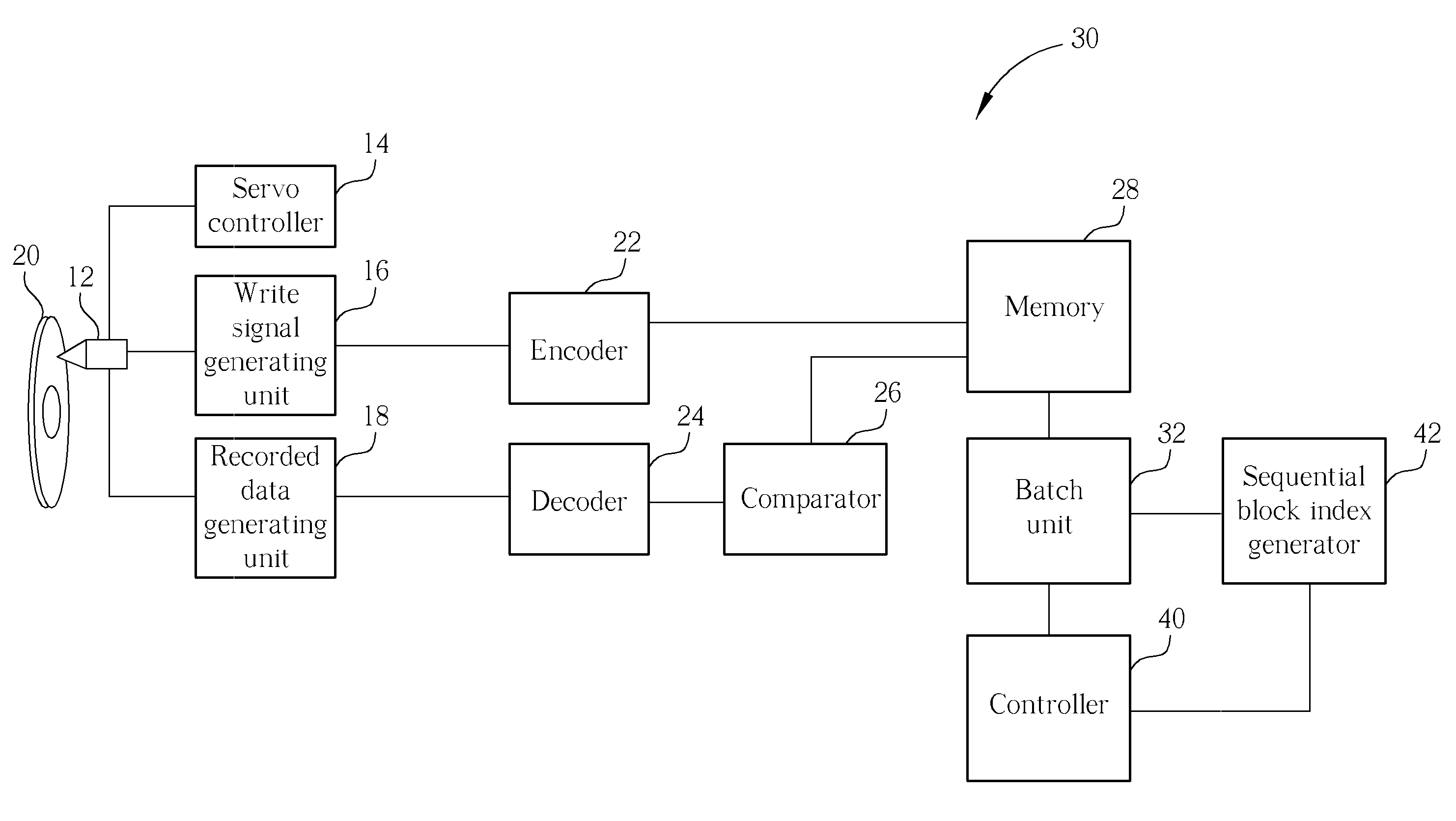
[0023]Please refer to FIG. 5. FIG. 5 is a block diagram of an optical disc drive 30 according to the invention. The optical disc drive 30 comprises a pickup head 12, a servo controller 14, a write signal generating unit 16, a recorded data generating unit 18, an encoder 22, a decoder 24, a comparator 26, a memory 28, a controller 40, a sequential block index generator 42 and a batch unit 32. The similar elements denoted as the same numerical have the similar function and structure as shown in FIG. 1. Therefore, the details are not described here for the sake of brevity.

[0024]The memory 28, for example a ring buffer, is divided into multiple blocks served as a basic unit for storing data. Each block is identified by a block index. The data stored in each block of the memory 28 having destination address information is to be recorded in a destination address of the optical disc 20. The destination address information could be a physical address or a logical address. In general, if a p...


PUM


Abstract

A control unit accesses a memory. The memory includes a plurality of blocks. The control unit includes a batch buffer, a batch controller and a multiplexer. The batch buffer stores a batch which includes a designated block index. The batch controller fetches the designated block index from the batch buffer. The multiplexer selectively outputs a sequential block index or the designated block index as an active index according to a control signal. And a designated block of the memory is accessed according to the active index.

Description

BACKGROUND OF THE INVENTION[0001]1. Field of the Invention[0002]The invention relates to a method and apparatus for accessing a memory, and more particularly, to a method and apparatus for accessing a ring buffer memory.[0003]2. Description of the Prior Art[0004]Please refer to FIG. 1. FIG. 1 is an exemplary block diagram of an optical disc drive 10. The optical disc drive 10 comprises a pickup head 12, a servo controller 14, a write signal generating unit 16, a recorded data generating unit 18, an encoder 22, a decoder 24, a comparator 26 and a memory 28. The servo controller 14 drives the pickup head 12 to read or write data from or to an optical disc 20. The memory 28 stores data. The data stored in the memory 28 are encoded by the encoder 22 to form an encoded recording data. The write signal generating unit 16 receives the encoded recording data and outputs a write signal to the pickup head 12 for recording the data onto an optical disc 20.[0005]The recorded data generating uni...

Claims


Application Information

Patent Timeline
IPC IPC(8): G11B7/085
CPCG11B20/10527G11B27/11G11B2020/10629G11B2020/10666G11B2220/2537G11B2020/10759G11B2020/10777G11B2020/10796G11B2020/10685
InventorLIU, TUN-HSINGCHEN, CHIH-CHUANYANG, KUN-CHIEH
OwnerMEDIATEK INC