Low power voice coil motor with a guiding magnet shell

Inactive Publication Date: 2010-04-01
VASSTEK INT
View PDF3 Cites 1 Cited by
  • Summary
  • Abstract
  • Description
  • Claims
  • Application Information

AI Technical Summary

Benefits of technology

[0010]The present invention is directed to a low power voice coil motor (VCM) with a guiding magnet shell, wherein attractive force in lateral direction between a magnetic device and a shell of the VCM causes friction force between a lens carrier and a plurality of guide posts. The added friction force is sufficient to maintain the lens carrier and other devices thereon at a specific position without applying the current to a coil. Furthermore, both the design and the assembling process of the lens carrier are simplified.
[0012]Furthermore, optical axis deviation under the movement of the lens carrier is improved by providing attractive force between the lens carrier and the plurality of guide posts to ensure close contact between them and to force the lens carrier into moving straightly.
[0013]To achieve low power, the shell is arranged at a distance within a predetermined range from the magnetic device, so that the magnetic device and the shell may attract each other laterally inducing a shift of the lens carrier and added the friction force between the plurality of guide posts and walls of a plurality of holes. The added friction force is larger than the gravitational force from a total weight of the magnetic device, the lens carrier and a lens set held by the lens carrier, and / or an upward attractive force of the shell on the magnetic device to maintain the lens set at a fixed position adjusted using the coil even if power applied to the coil is turned off.

Problems solved by technology

However, the current is consumed continuously depend on the maintaining time in order to maintaining the location of carrier so that it can not satisfy low power design requirement for portable devices.
However, the lens carrier 45 with the opening curved surface 51 and the through-hole 52 is too complicated for fabricating the lens carrier 45.

Method used


Image

  • Low power voice coil motor with a guiding magnet shell
  • Low power voice coil motor with a guiding magnet shell
  • Low power voice coil motor with a guiding magnet shell

Examples


Embodiment Construction

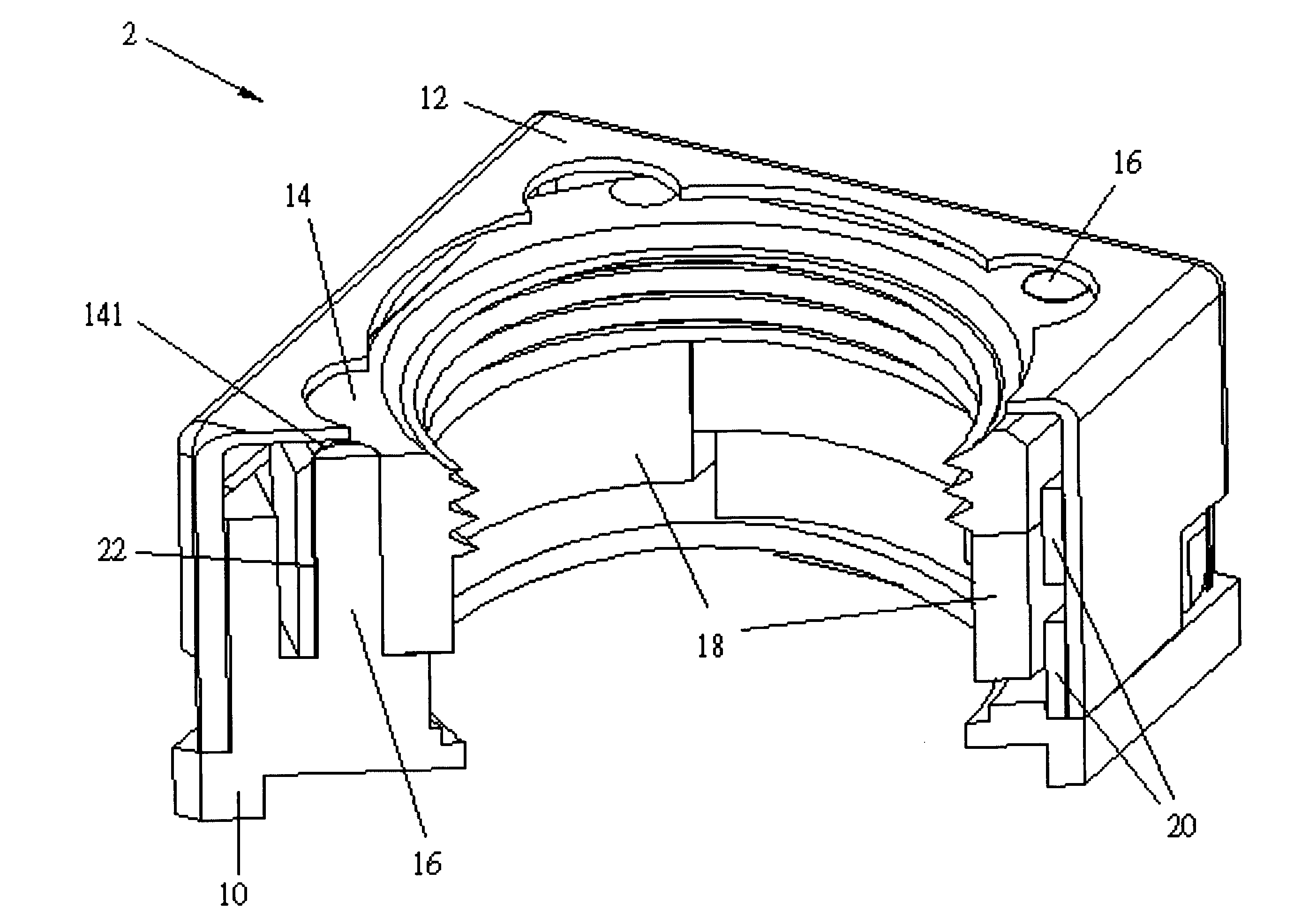
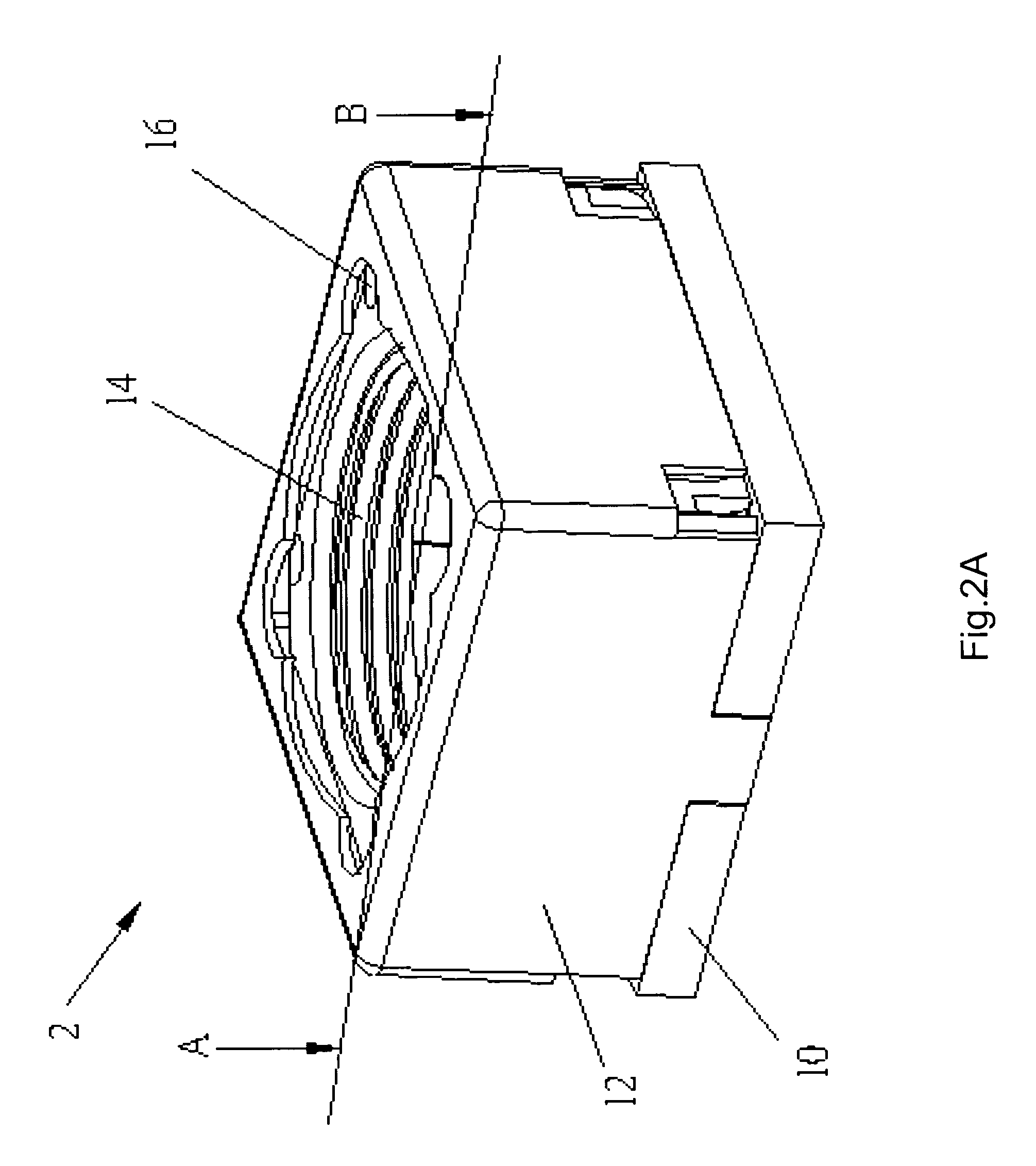
[0018]Please refer to FIG. 2A and FIG. 2B in correspondence with the following description. FIG. 2A and FIG. 2B are schematic diagrams illustrating a voice coil motor (VCM) according to some aspects of the present invention. As illustrated in FIG. 2A, a VCM 2 comprises a base 10, a shell 12 disposed on the base 10, a lens carrier 14 enclosed by the shell 12 and a plurality of guide posts 16 passing through the lens carrier 14. FIG.2A may be cross sectioned along line AB to be observed as a three dimensional structure as depicted in FIG. 2B.

[0019]As illustrated in FIG. 2B, the VCM 2, except for above-mentioned components, further comprises the plurality of guide posts 16 on the base 10, an electromagnetic driving apparatus (mainly constructed by a coil 20), and a magnetic device 18 physically connected with the lens carrier 14.

[0020]Briefly, the magnetic device 18 attracts the shell 12 in lateral direction, denoted as lateral attractive force T as shown in FIG. 3A, so as to the later...


PUM


Abstract

A low power voice coil motor (VCM) with a guiding magnet shell comprises a magnetic device, a lens carrier, a base, a plurality of guide posts, an electromagnetic driving apparatus and a shell enclosing the lens carrier, the magnetic device and the electromagnetic driving apparatus. The shell and the magnetic device are arranged with a distance within a predetermined range and the attractive force between the magnetic device and the shell in lateral direction induces a shift of the lens carrier for added the friction force between the plurality of guide posts and walls of a plurality of holes. The added friction force is larger than a gravitational force from a total weight of the magnetic device, the lens carrier and a lens set held by the lens carrier, and / or an upward attractive force of the shell on the magnetic device, so the lens set can be fixed at a position even if power is turned off.

Description

BACKGROUND OF THE INVENTION [0001]1. Field of the Invention[0002]The present invention relates to a voice coil motor, and more particularly, to a voice coil motor with low power capability by a guiding magnet shell.[0003]2. Description of the Prior Art[0004]In order to perform a more accurate position control for a set of lenses or an access arm of a hard disk drive, a voice coil motor (VCM) is adopted to move the set of lenses or the access arm of the hard disk drive. The structure of a VCM is primarily a coil placed within a magnetic path including a permanent magnet.[0005]In an optical system employing a VCM, an interaction propelling force between the coil and the permanent magnet according to Fleming's left-hand rule to move a carrier physically connected to the permanent magnet when a current flows through the coil; at the same time, a set of lenses which is attached to the carrier is moved correspondingly, so as to achieve optical zoom and focus functionalities. Based on appl...

Claims


Application Information

Patent Timeline
IPC IPC(8): G11B21/08
CPCG11B5/5569
Inventor LEE, SHIH-CHUAN
Owner VASSTEK INT
Why Eureka
Try Eureka