Transfer control mechanism for printer and transfer control method

a control mechanism and printer technology, applied in the field of conveying control mechanism, can solve the problems of wasting recourses, damage to the recording head, failure to record on the sheet according to the settings, etc., and achieve the effect of easy removal of the sh

Active Publication Date: 2010-04-08
RISO KAGAKU CORP
View PDF4 Cites 13 Cited by
  • Summary
  • Abstract
  • Description
  • Claims
  • Application Information

AI Technical Summary

Benefits of technology

[0039]According to the above-described configuration, when a sheet trouble occurs in the printing machine having the switchback route, the sheets retaining inside the switchback route are conveyed to the image forming route in the step o...

Problems solved by technology

If a sheet curls considerably upward, the interval between the sheet and a recording head deviates from a preset interval, thereby causing a failure in recording on the sheet according to the settings.
In some other cases, the sheet may strike against the recording head and may damage the recording head as a consequence.
Removal of all the sheets on the conveyance route at the time of a jam release operation for a jammed sheet complicates the jam release operation, and also causes a waste of recourses because numerous usable sheets are wastefully discarded.
In the latter case, if a belt platen continues the operation to convey the sheet, a recording head may be damaged.
Therefore, the curled sheet also passes through a belt platen unit and thereby may damage a recordin...

Method used


Image

  • Transfer control mechanism for printer and transfer control method
  • Transfer control mechanism for printer and transfer control method
  • Transfer control mechanism for printer and transfer control method

Examples


first embodiment

(Overall Configuration of Printer)

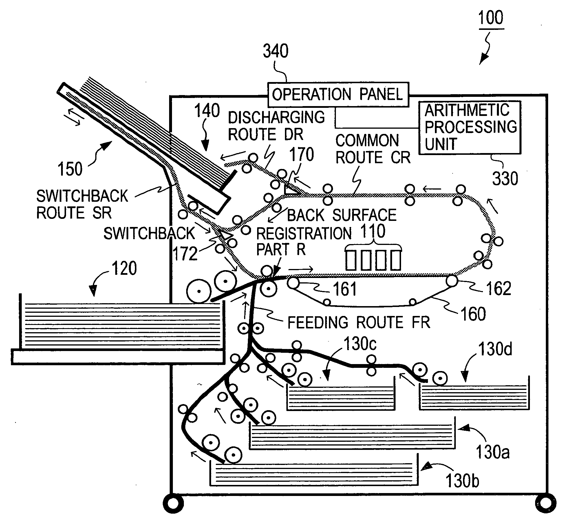
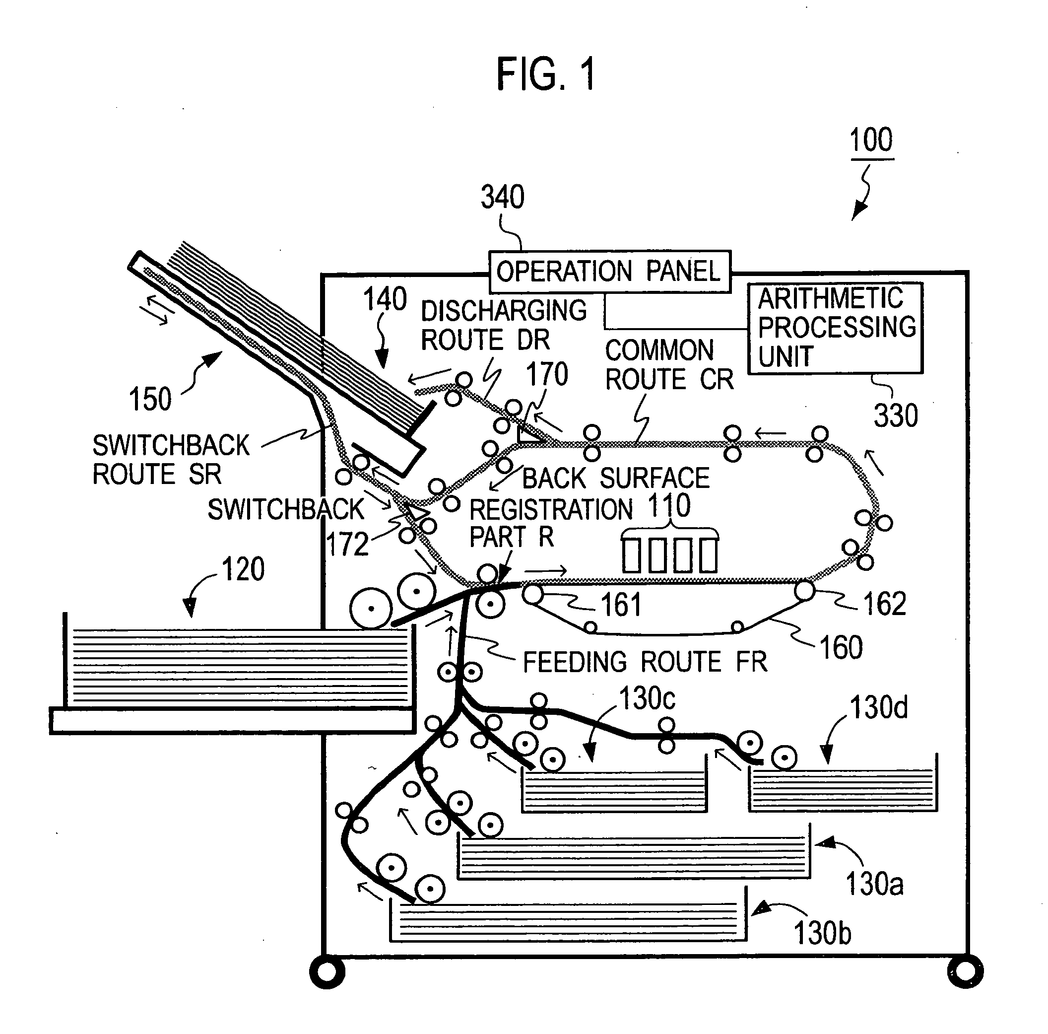
[0051]FIG. 1 is a configuration diagram showing an outline of a print sheet conveyance route of a printer 100 according to a first embodiment of the present invention. In the first embodiment, the printer 100 is described by taking an inkjet line color printer as an example, which includes multiple ink heads each provided with numerous nozzles and is configured to perform printing on a line basis by ejecting black or color inks out of the ink heads respectively and to form multiple images on a recording sheet on a conveyance belt so that the images overlap each other.

[0052]As shown in FIG. 1, the printer 100 is an apparatus configured to form images on a surface of a sheet which is conveyed on an annular conveyance route. The conveyance route essentially includes a feeding route FR to feed sheets, a common route CR continuing from the feeding route FR to a sheet discharging route DR through a head unit 110, and a switchback route SR which is branche...

second embodiment

[0096]Next, a second embodiment of the present invention will be described with reference to the accompanying drawings. The “overall configuration of the printer” of the second embodiment is the same as that of the first embodiment so that the redundant explanation is omitted herein. Moreover, constituents having similar functions to those in the first embodiment will be denoted by similar reference numerals in the following description.

(Transfer Control Mechanism)

[0097]In the second embodiment, control of the sheet conveyance mechanism is executed by the arithmetic processing unit 330. FIG. 7 is a block diagram showing a module of the sheet conveyance mechanism according to the second embodiment. As shown in FIG. 7, the module of the sheet conveyance mechanism includes a jam detector 331, an emergency stop mechanism 332, a conveyance route controller 333, and a discharge controller 334.

[0098]The jam detector 331 is the module configured to detect occurrence of a trouble on the conv...


PUM


Abstract

A conveyance control mechanism for a printer including an image forming unit forming an image on a sheet being conveyed on a conveyance route, includes a curl detector configured to detect a curl of the sheet conveyed on the conveyance route, in an upstream of the image forming unit on the conveyance route. The conveyance route controller may drive and stop the conveyance route differently depending on whether the curl detector detects a curl at either a front end or at a position other than the front end. When the curl detector detects a curl of the sheet, an image forming route where the image forming unit performs an image formation may be separated and retreated from the conveyance route and the sheet being conveyed may be discharged onto the retreated image forming route.

Description

CROSS REFERENCE TO RELATED APPLICATION[0001]This application is based upon and claims the benefit of priority from the prior Japanese Patent Application No. 2008-257778 filed on Oct. 2, 2008 and the prior Japanese Patent Application No. 2008-309928 filed on Dec. 4, 2008, the entire contents of which are incorporated herein by reference.BACKGROUND OF THE INVENTION[0002]1. Field of the Invention[0003]The present invention relates to a conveyance control mechanism for a printer provided with an image forming unit configured to form an image on a surface of a sheet conveyed on a conveyance route, and relates to a conveyance control method.[0004]2. Description of the Related Art[0005]In general, in order to record an image on a sheet, an inkjet-type image forming apparatus constantly needs to maintain an interval between a sheet and multiple recording nozzles of a printing head at an optimum distance for recording.[0006]A sheet may often curl above a sheet conveyance unit. If a sheet cur...

Claims


Application Information

Patent Timeline
IPC IPC(8): G03G15/00
CPCG03G2215/00552G03G15/6561G03G2215/00662G03G2215/00628
Inventor HARA, MASASHIMAEDA, YUKIHIROFUJIMOTO, MASATOSHIKAWANO, MASAKAZU
Owner RISO KAGAKU CORP
Why Eureka
Try Eureka