Laser ignition for gas mixtures

a gas mixture and gas ignition technology, applied in the direction of ignition sparking plugs, combustion engines, machines/engines, etc., can solve the problems of mixture extinguishing, gas mixture ignition not igniting with the desired reliability, and extremely small ignition cores, so as to avoid the risk of uncontrolled glow ignition, reliable ignition, and reduce heat loss

Active Publication Date: 2010-06-17
MULTIFLASHLIGHT
View PDF14 Cites 52 Cited by
  • Summary
  • Abstract
  • Description
  • Claims
  • Application Information

AI Technical Summary

Benefits of technology

[0027]The effect of a highly transient temperature control is that, before and after the ignition phase, all the wall temperatures in the laser hot-spot system lie reliably below the ignition temperature. The risk of uncontrolled glow ignitions is therefore avoided. With the conventional structure with metallic ignition electrodes and a ceramic spark plug foot, on the other hand, there is always the risk of glow ignitions, since limited surface zones give rise to glow ignitions due to insufficient heat being carried away.
[0028]Better ignition conditions arise due to the small-eddy turbulence structure inside the prechamber. The more reliable ignition with hot-spot systems requires that the mixture touches the hot surface with, as far as possible, small-eddy turbulence. As a result, the energy requirement due to the small dimensions of th...

Problems solved by technology

These laser ignitions do not ignite with the desired reliability.
An essential drawback with such laser ignitions consists in the fact that they only generate an extremely small ignition core, wherein very markedly fluctuating charge states (composition, temperature, speed, turbulence) exist locally at the ignition site in connection with the comparatively large-eddy flow and turbulence structure in the combustion chamber, especially of large gas engines.
Furthermore, there is in the lean operation the particular problem that the mixture is extinguished again immediately after ignition, since too much heat is removed from the inner cone of the flame.
For the aforementioned reasons, therefore, the ignition and combustion potential of laser ignition has hitherto not been able to be fully utilised.
In the case of longer-term operation, contamination and deposits also arise ...

Method used


Image

  • Laser ignition for gas mixtures
  • Laser ignition for gas mixtures
  • Laser ignition for gas mixtures

Examples


Embodiment Construction

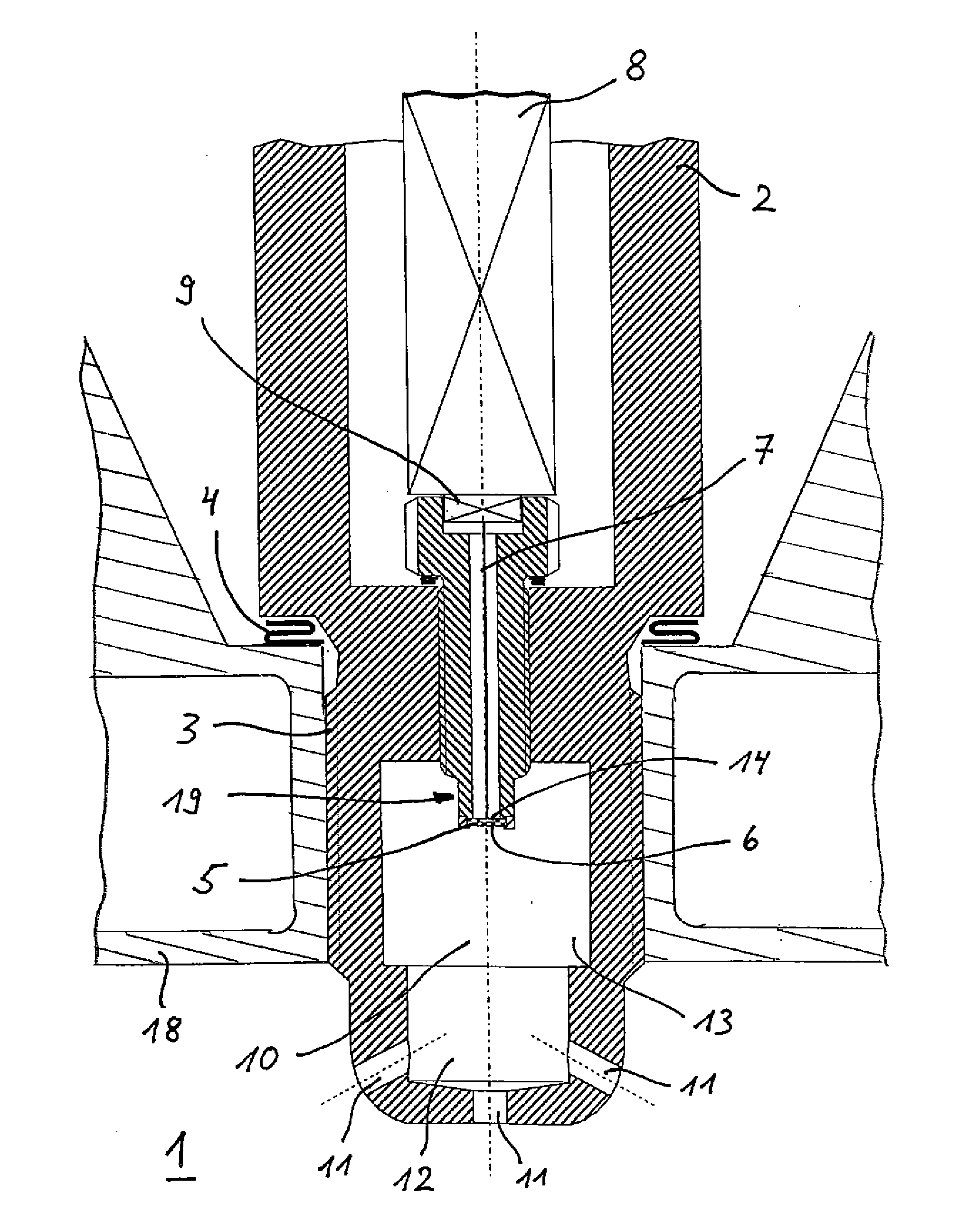
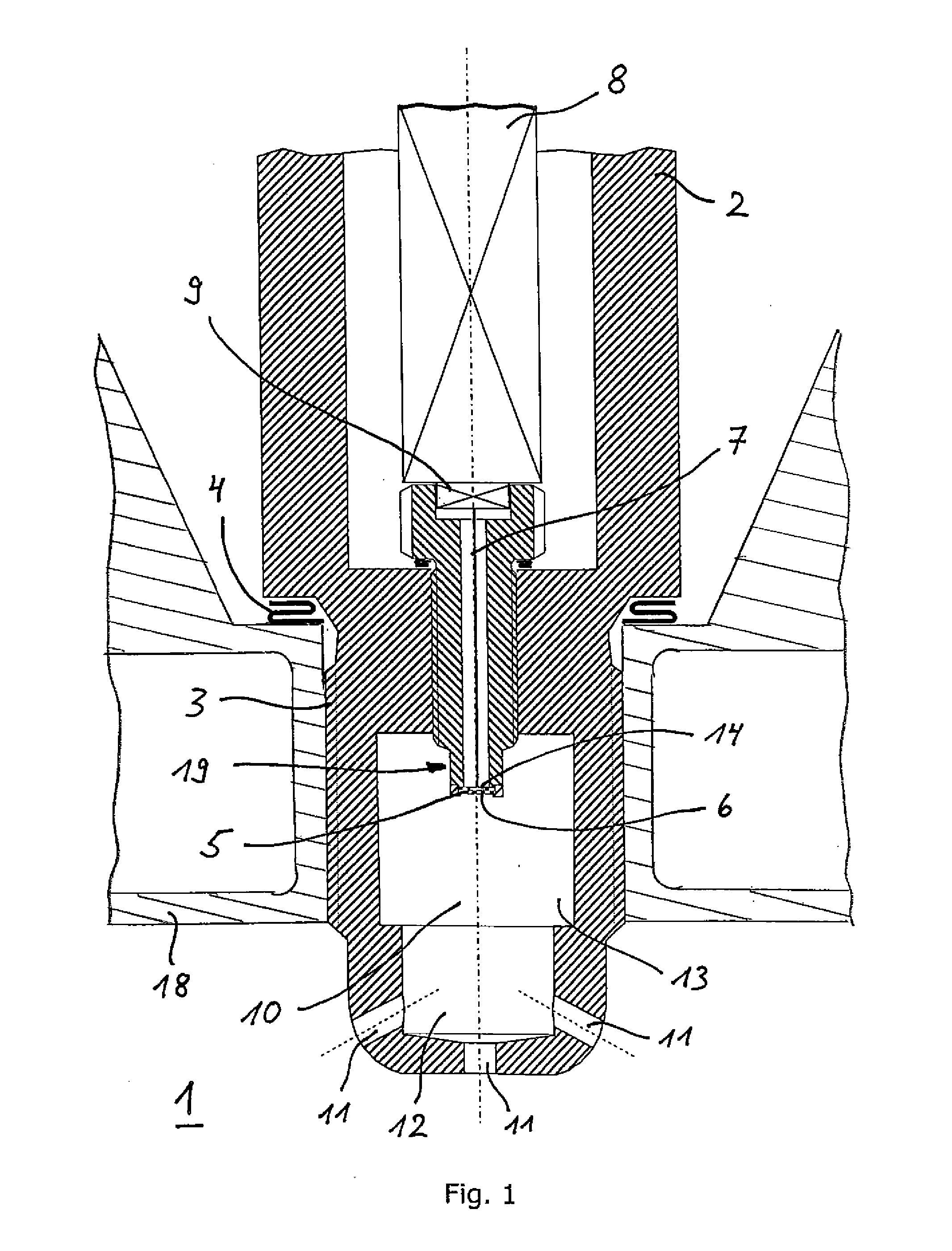
[0043]FIG. 1 shows an ignition device according to the invention for the ignition of a combustible or explosive gas mixture in a main combustion chamber 1, in particular for the ignition of a fuel-air mixture or a combustion gas-air mixture in an internal combustion engine. With a hot-spot laser ignition according to the prior art, i.e. without prechamber 10, main combustion chamber 1 is the same as the combustion chamber ignited from the hot-spot. The ignition device is designed in the form of a spark plug 2 which can be mounted in the wall of a cylinder head 18. For this purpose, spark plug 2 comprises an external thread 3 and a gasket 4, with which it can be screwed in a sealed manner into the wall of cylinder head 18. It comprises a high temperature-resistant absorber body 5, which is arranged in contact with gas mixture coming from main combustion chamber 1, with a combustion chamber inner side 6 facing the gas mixture, i.e. the gas mixture in a prechamber 10.

[0044]Spark plug 2...


PUM


Abstract

An ignition device for the ignition of a gas mixture in a main combustion chamber (1), in particular of an internal combustion engine, is proposed, wherein the absorber body (5) is heated by means of a laser (8). A prechamber (10) is located upstream of the absorber body (5) on the combustion chamber inner side (6) in order to improve the ignition behaviour.

Description

[0001]The invention relates to the area of the laser ignition of gas mixtures. It is directed in particular towards an ignition device for the ignition of a combustible or explosive gas mixture in a main combustion chamber, in particular for the ignition of a fuel-air mixture or a combustion gas-air mixture in an internal combustion engine, comprising a high temperature-resistant absorber body, which is arranged in contact with gas mixture coming from the main combustion chamber and which comprises a combustion chamber inner side facing the gas mixture, and a light guide path for guiding a laser beam onto the absorber body in order to heat the absorber body with the laser beam until an ignition temperature required for the ignition of the gas mixture is reached on the combustion chamber inner side of the absorber body, wherein the light guide path up to the absorber body is configured in such a way that the laser beam does not have direct contact with the gas mixture of the main com...

Claims


Application Information

Patent Timeline
IPC IPC(8): F02B19/00F02P23/04
CPCF02P23/04F02P13/00
Inventor KUHNERT, DIETERKETTNER, MAURICEMAUL, GEORG
Owner MULTIFLASHLIGHT
Why Eureka
Try Eureka