Photodetector, method for manufacturing the same, and photodetection system

a technology of photodetector and manufacturing method, which is applied in the field of photodetector, can solve the problems of difficult mass production of devices, difficult positioning and time-consuming, etc., and achieve the effect of low cost and high precision

Inactive Publication Date: 2010-09-09
TDK CORPARATION
View PDF0 Cites 61 Cited by
  • Summary
  • Abstract
  • Description
  • Claims
  • Application Information

AI Technical Summary

Benefits of technology

[0007]In view of the foregoing problems, various exemplary embodiments of this invention provide a photodetector which enables the positioning of the photodetector and the positioning of an optical aperture such as a pinhole to be made at one time when an optica

Problems solved by technology

Therefore, the positioning is difficult and time consuming.

Method used


Image

  • Photodetector, method for manufacturing the same, and photodetection system
  • Photodetector, method for manufacturing the same, and photodetection system
  • Photodetector, method for manufacturing the same, and photodetection system

Examples


Embodiment Construction

[0051]Hereinafter, a photodetector according to preferred exemplary embodiments of the present invention, a photodetection system using the same, and a method for manufacturing the photodetector will be described.

Exemplary Embodiments

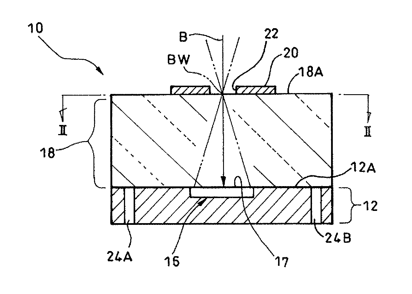
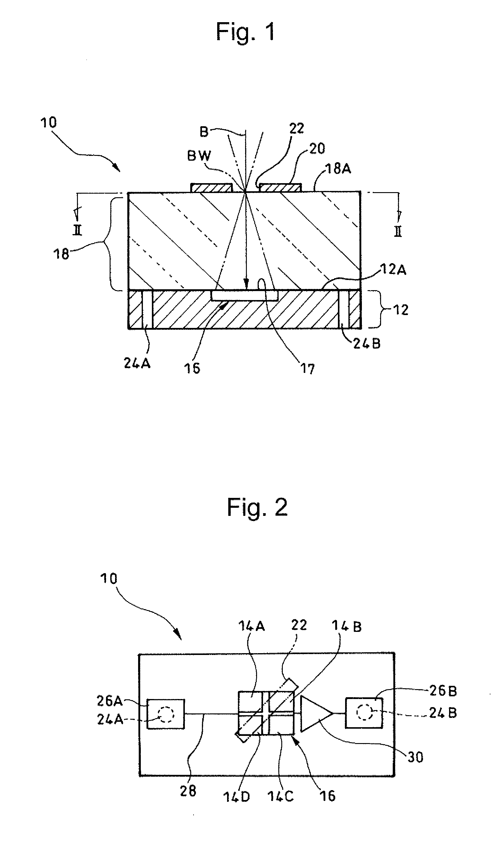
[0052]As shown in FIGS. 1 and 2, a photodetector 10 according to a first exemplary embodiment of the present invention is configured to include: a photodetection unit 16 including four photodetection elements 14A, 14B, 14C, and 14D (which may be collectively referred to as photodetection elements 14) that are embedded and arranged in a flat surface (upper surface) 12A of a semiconductor chip 12; a light transmitting unit 18 that is disposed on a light receiving surface 17 side of the photodetection unit 16 (the side thereof opposite to the semiconductor chip 12) so as to cover the photodetection unit 16; a light shielding layer 20 that shields an incident light beam B and is deposited on a surface 18A of the light transmitting unit 18 (the surface on th...


PUM


Abstract

A photodetector used in, for example, an optical pickup device includes: a photodetection unit including a plurality of photodetection elements and provided on a semiconductor chip; a light transmitting unit formed on the upper surface of the photodetection unit; and a light shielding layer having an optical aperture and disposed on the upper surface of the light transmitting unit, with these components being formed integrally. The light transmitting unit is configured such that the distance between the optical aperture and the photodetection unit is maintained constant, and the optical aperture is formed such that the inner portion of an incident light beam passes therethrough. The positioning of the photodetector and the positioning of the optical aperture such as a pinhole or a slit for adjusting the light beam entering the photodetection elements of the photodetector can be made at the same time.

Description

BACKGROUND OF THE INVENTION[0001]1. Field of the Invention[0002]The present invention relates to a photodetector, and in particular to a photodetector suitably used in an optical head device for recording and reproducing information on and from an optical recording medium, to a method for manufacturing the photodetector, and to a photodetection system using the photodetector.[0003]2. Description of the Related Art[0004]Japanese Patent Application Laid-Open No. Hei 8-185640 discloses an optical pickup device for a dual-layer optical disc that can detect servo signals accurately to perform control operations in a reliable manner.[0005]This optical pickup device is configured to include: a photodetector that receives a light beam reflected from a dual-layer optical disc; a beam splitter; a first focusing lens that is disposed between the photodetector and the beam splitter such that their optical axes coincide with each other; a light shielding plate that shields the beam reflected fro...

Claims


Application Information

Patent Timeline
IPC IPC(8): H01L31/0232H01L31/09H01L31/0216H01L31/18
CPCG11B7/131G11B7/22G11B7/1381G11B7/133
Inventor KAWANO, NORIYUKINISHIYAMA, TETSUYANISHIMURA, HIRONOBUISHIDA, TOMOHIKO
Owner TDK CORPARATION
Why Eureka
Try Eureka