Reflective Camouflage and Methods

a technology of reflective camouflage and mask, applied in the field of reflective camouflage and methods, can solve the problems of blinds being rendered ineffective, particular patterns or shades chosen for one season or one location may not be effective in another season or another location, and the camouflage may be ineffective to conceal the position or observer, etc., to achieve effective concealment, improve the ability of hunters, and be convenient to carry.

Inactive Publication Date: 2010-09-16
LEWIS JR ROGER +1
View PDF4 Cites 12 Cited by
  • Summary
  • Abstract
  • Description
  • Claims
  • Application Information

AI Technical Summary

Benefits of technology

[0012]Additional embodiments are provided for a temporary, easily portable camouflage system. A reflective coating is provided on a fabric, paper, foil or other flexible material. A temporary, portable frame, such as a pop-up tent frame of flexible wire, fiberglass shock cord frame, nesting legs and scissor top frame, umbrella type frame or other collapsible, foldable or rollable frame is erected. The reflective exterior is then added such that the sides of the temporary enclosure form sides inclined outwardly from the center. Observation ports, gun ports, camera ports or bow ports are provided using two-way reflective materials so that the observer inside the enclosure may observe game or other surroundings, while remaining totally concealed from an onlooker or game looking at the enclosure.
[0013]A portable shield having a frame or lightweight panel embodiment is provided. The panel or frame is again covered with mirrored or reflective material, and at least a portion, or alternatively the entire shield, is provided as a two-way reflective material. The material may be a cloth, foil or sheet of material that is temporarily mounted on the frame when the frame is in use, or a permanent material comprised of one or more panels. In some embodiments, the shield may roll or fold, and be stored in a carrier with straps and a protective cover. The shield may include legs or supports to ensure that when in use facing game or another observer, the shield is maintained at the proper inclination to prevent reflections from the sun or the

Problems solved by technology

A problem with the prior art patterned type of camouflage is that the covering may not match the foreground or background, thus the camouflage may be ineffective to conceal the position or observer.
For example, a particular pattern or shade chosen for one season or for one location may not be effective in another season or another location.
Thus, the blind is rendered ineffective when conditions change or when moved to another location.
The inventors of the present application have previously determined that material oriented in this direction fails to provide effective concealment.
Although the structure will reflect to some extent the natural surroundings and thus be a match to the environment in different seasons or locations, the flaws make the camouflage less effective than

Method used


Image

  • Reflective Camouflage and Methods
  • Reflective Camouflage and Methods
  • Reflective Camouflage and Methods

Examples


embodiment 31

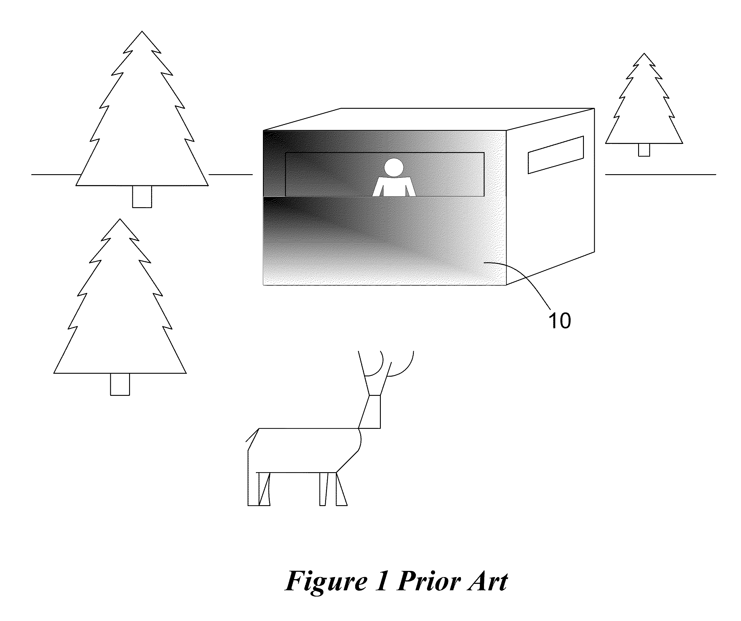
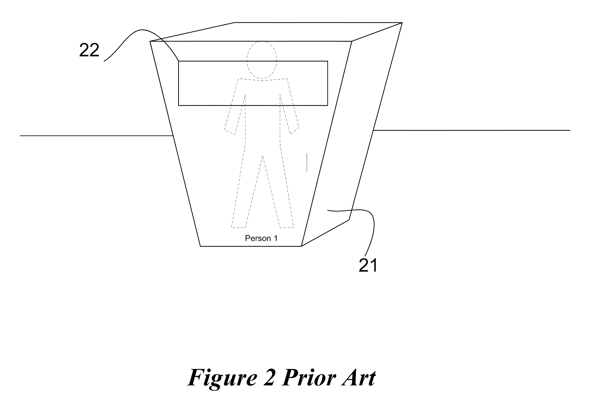
[0042]FIG. 3 depicts a first exemplary embodiment. FIG. 3 depicts an enclosure 31 which may be of various sizes. Typically, the enclosure will be of a sufficient height to conceal a person standing within, and of sufficient volume to enable comfortable use of a gun, camera, or other equipment, and may be larger for multiple observers, for example. Smaller, lighter enclosures for prone or sitting positions may be fabricated as well. The embodiment 31 of FIG. 3 is a four sided deer or duck blind embodiment that may be used, for non limiting examples, to hunt game such as deer, wild pigs, coyotes, elk, moose etc., or birds, including waterfowl, or to observe game, photograph, perform research on animal behaviors and the like. Hunting may be performed with a ballistic weapon including a rifle, a bow, pistol, cross bow or the like. The use of four sides is but one example; ovals, circles, and three sided, octagonal, and other shapes are also contemplated as further described below.

[0043]...

embodiment 214

[0060]FIG. 13 depicts an alternative embodiment 214 using a collapsible top framing system 217 with collapsible or nesting extensible poles 219 for legs. The scissored top structure 217 allows the corners of the unit to be pushed together and form a small rectangular volume for storage. By using the flexible covering with a mirrored surface, the entire structure can collapse into a suitcase sized carry bag or duffel bag for portability. Alternatively, removable folding panels could be used on the exterior. The enclosure is height adjustable.

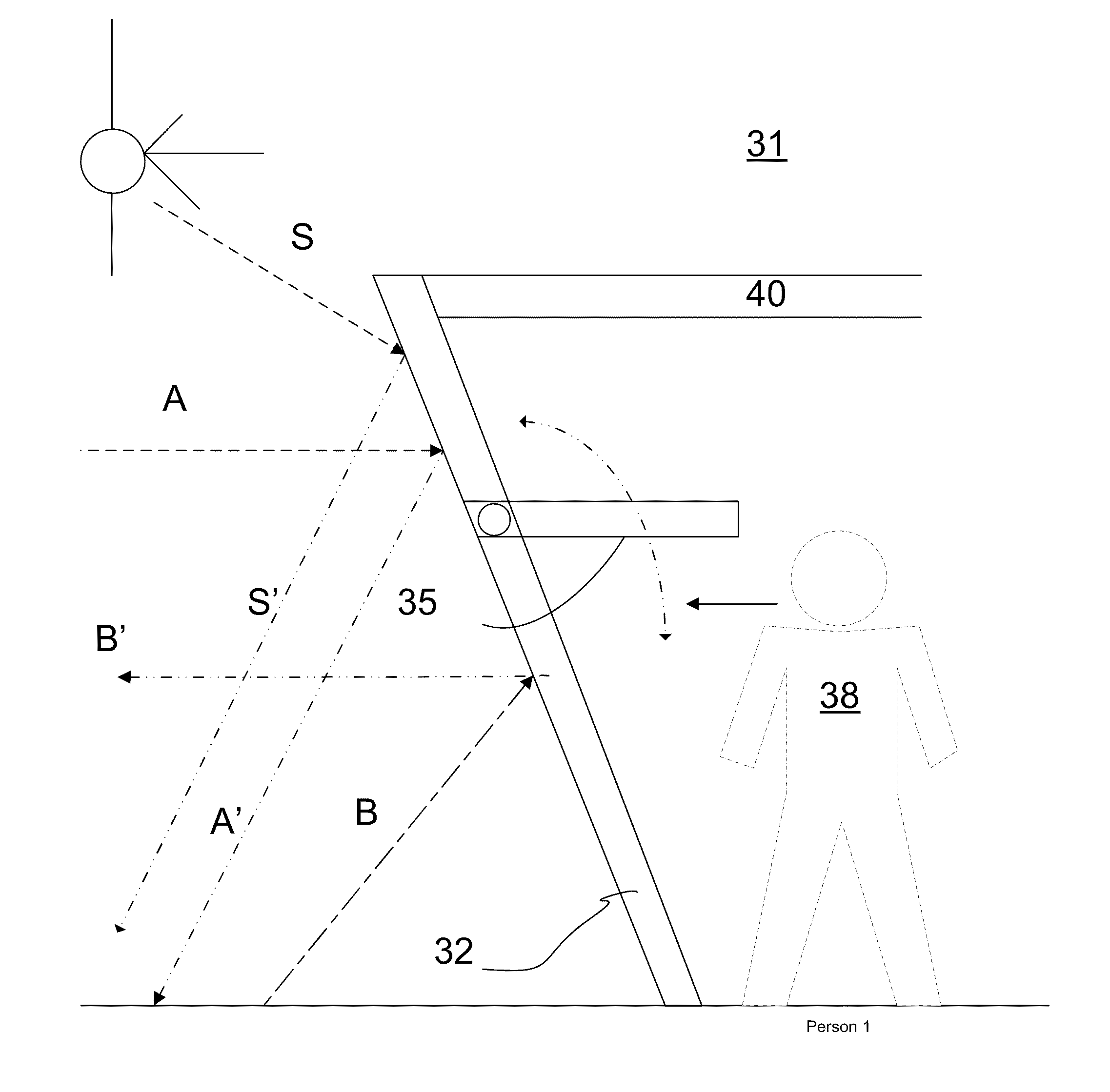
[0061]Note that any enclosure of the embodiments can be made large enough to provide, in addition to concealment, shelter, storage and living quarters, as the embodiments are not limited in size. For a military application, an enclosure incorporating the concealment may be large enough for a platoon or squadron, or even larger. Size is not limited; the concealment is achieved by use of the reflective material inclined towards the horizontal to re...


PUM


Abstract

Methods and system for providing concealing camouflage of a position, hunter or observer using a shield or enclosure with a reflective exterior having exterior sides inclined towards the horizontal and observation portions of two-way mirror material. The shield or enclosures may be of any shape and may be of rigid sides permanently affixed to a frame, or be provided as collapsible or pop-up enclosures using temporary attachments and frames or poles. The enclosures may be entirely of two-way material. The reflective material may be mirror glass, any clear material treated on one surface with mirror coatings, or metalized cloth or film, including metalized polyester. A roof may be provided as non-reflective or reflective and may be flat or dome shaped. Two-way mirrored observation ports that open and close may be provided in any shape or position. The enclosure may conceal a boat, raft, or vehicle.

Description

[0001]This application claims the benefit of U.S. Provisional Application No. 61 / 159,687, entitled “Reflective Camouflage and Methods,” filed on Mar. 12, 2009, which is incorporated herein by reference.TECHNICAL FIELD[0002]The present invention relates generally to an apparatus and methods for camouflaging an enclosure. The enclosure or other position is camouflaged using a reflective surface on the exterior. More particularly, the present invention relates to methods and an apparatus for providing camouflage by providing an enclosure with a reflective outer surface positioned so as to provide a reflected image of the foreground to any observer, while providing the enclosure with reflective covered two-way mirrored observation ports or shooting ports for an observer or for a mechanism such as a sensor or camera. The observer or mechanism is effectively hidden from view by the reflective camouflage.BACKGROUND[0003]Generally, camouflage of an observer position is achieved by providing...

Claims


Application Information

Patent Timeline
IPC IPC(8): G02B27/10
CPCA01M31/025F41H3/00E04H15/001
Inventor LEWIS, JR., ROGERLEWIS, SR., ROGER
Owner LEWIS JR ROGER
Why Eureka
Try Eureka