Image processing apparatus and image processing method

Inactive Publication Date: 2010-10-28
RENESAS ELECTRONICS CORP
View PDF3 Cites 0 Cited by
  • Summary
  • Abstract
  • Description
  • Claims
  • Application Information

AI Technical Summary

Benefits of technology

[0010]According to the first aspect of the present invention, the adjustment value is generated based on the positional information of the pixel, and the correction value is changed based on the adjustment value. In other words, the correction value in the filter processing is changed based on the positional information of the pixel. Hence, the symptom caused by receiving the influence of the pixel of the range in which the filter processing is not performed can be rectified in the boundary between the range in which the filter processing is performed and the range in which the filter processing is not performed. More specifically, for example, by changing the correction value based on the positional information indicating the boundary part between the range in which the filter processing is performed and the range in which the filter processing is not performed, this symptom can be rectified.
[0011]Further, unlike the related arts, there is no need to copy the pixel corresponding to the end part in the range in which the filter processing is performed. Therefore, there is no need to add the hardware configuration for the copy processing. Furthermore, since the control of this copy processing is not required, the whole processing can be readily controlled even when the number of taps of the filter is increased.
[0014]According to the second aspect of the present invention, the adjustment value is generated based on the positional information of the pixel, and the correction value is changed based on the adjustment value. In other words, the correction value in the filter processing is changed based on the positional information of the pixel. Thus, the symptom caused by receiving the influence of the pixel of the range in which the filter processing is not performed can be rectified in the boundary between the range in which the filter processing is performed and the range in which the filter processing is not performed. More specifically, for example, by changing the correction value based on the positional information indicating the boundary part between the range in which the filter processing is performed and the range in which the filter processing is not performed, this symptom can be rectified.
[0015]Furthermore, unlike the related arts, there is no need to copy the pixel corresponding to the end part in the range in which the filter processing is performed. Hence, there is no need to add the hardware configuration to realize this copy processing. In addition, since the control of the copy processing is not required even when the number of taps of the filter is increased, the whole processing can be readily controlled.
[0017]According to the present invention, it is possible to readily rectify the symptom caused in the boundary part between the range in which the filter processing is performed and the range in which the filter processing is not performed.

Problems solved by technology

However, due to the influence of the pixel of the range in which the filter processing is not executed in a boundary between a range in which the filter processing is executed and a range in which the filter processing is not executed, a symptom may be caused in the image after the filter processing is performed.
Moreover, increase of the number of taps of the filter makes it difficult to control the copy processing.

Method used


Image

  • Image processing apparatus and image processing method
  • Image processing apparatus and image processing method
  • Image processing apparatus and image processing method

Examples


first exemplary embodiment

[0031]Hereinafter, the exemplary embodiments of the present invention will be described with reference to the drawings.

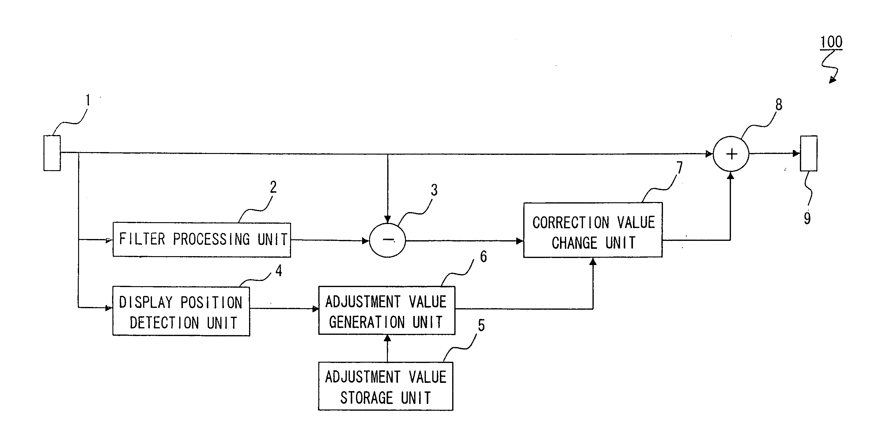
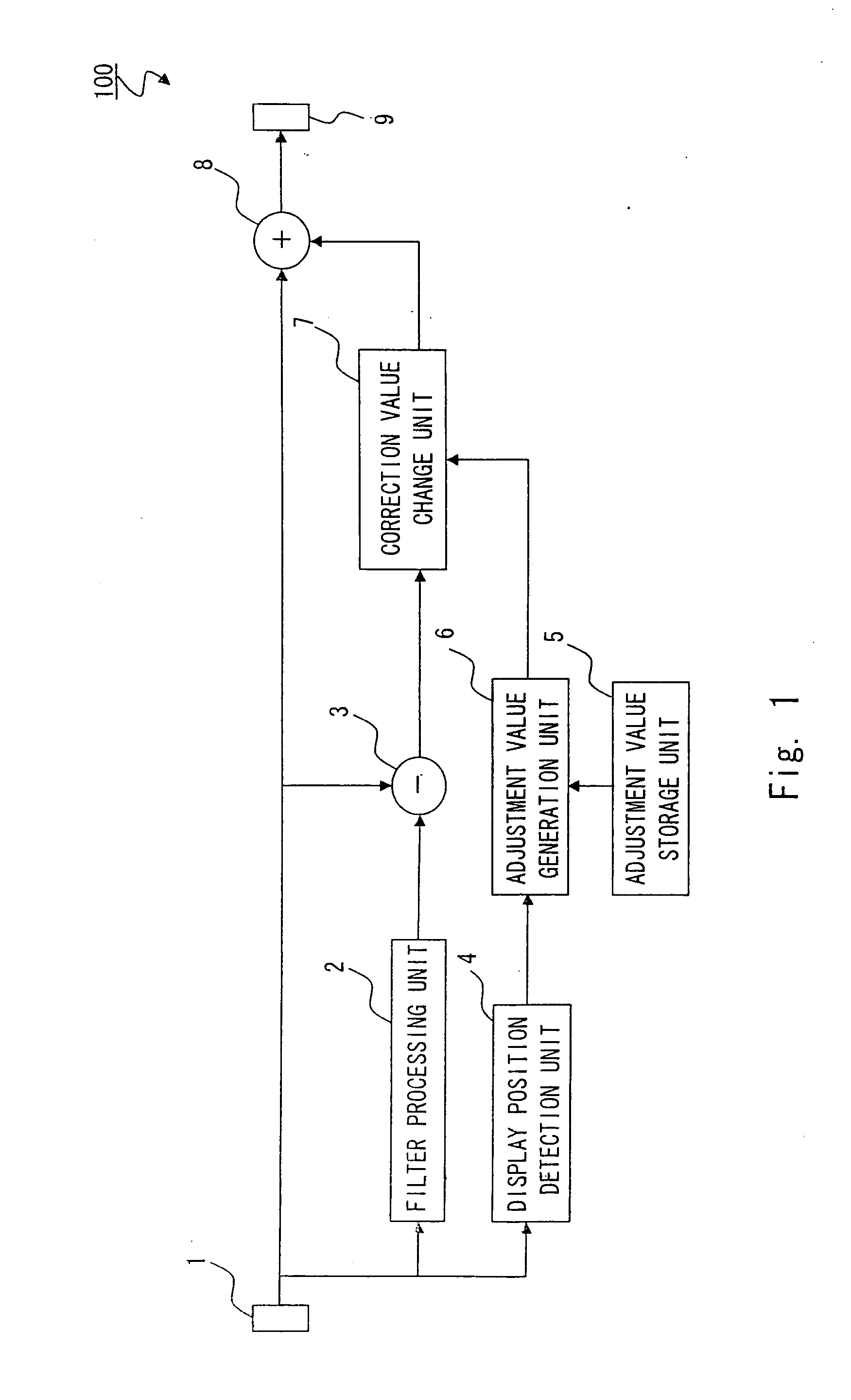
[0032]FIG. 1 is a block diagram showing one example of the configuration of an image processing apparatus 100 according to the first exemplary embodiment of the present invention. As shown in FIG. 1, the image processing apparatus 100 includes an input unit 1, a filter processing unit 2, a subtractor 3, a display position detection unit 4, an adjustment value storage unit 5, an adjustment value generation unit 6, a correction value change unit 7, an adder 8, and an output unit 9 and the like.

[0033]The image processing apparatus 100 further includes a control unit (not shown) formed by an FPGA (Field Programmable Gate Array) which is not shown, and the FPGA stores various programs for controlling each unit of the image processing apparatus 100. The control unit executes these various programs, so as to control each unit of the image processing apparatus 100. Note tha...

second exemplary embodiment

[0066]FIG. 8 is a block diagram showing one example of the configuration of an image processing apparatus 200 according to the second exemplary embodiment of the present invention. As shown in FIG. 8, the image processing apparatus 200 according to the second exemplary embodiment has the same configuration as that of the image processing apparatus 100 according to the first exemplary embodiment except for the configurations of a horizontal position detection unit 41, a vertical position detection unit 42, a horizontal adjustment value storage unit 51, a vertical adjustment value storage unit 52, a horizontal adjustment value generation unit 61, a vertical adjustment value generation unit 62, a horizontal gain adjustment unit 71, a vertical gain adjustment unit 72, and an adder 80. The same components are denoted by the same reference symbols, and the overlapping description will be omitted.

[0067]The horizontal position detection unit 41 detects the horizontal display position (horiz...


PUM


Abstract

An image processing apparatus that performs filter processing of image data includes a filter processing unit that performs filter processing by reflecting a correction value in a pixel value, an adjustment value generation unit that generates a gain value based on display position of a pixel, and a correction value change unit that changes the correction value based on the gain value generated by the adjustment value generation unit.

Description

INCORPORATION BY REFERENCE[0001]This application is based upon and claims the benefit of priority from Japanese patent application No. 2009-106194, filed on Apr. 24, 2009, the disclosure of which is incorporated herein in its entirety by reference.BACKGROUND[0002]1. Field of the Invention[0003]The present invention relates to an image processing apparatus and an image processing method, and more particularly, to an image processing apparatus and an image processing method to perform filter processing of image data.[0004]2. Description of Related Art[0005]In general, in filter processing of image data, each pixel of the image data is multiplied by a predetermined filter coefficient. For example, filter processing is executed with a filter having a predefined size of 3×3 pixels, for example.[0006]However, due to the influence of the pixel of the range in which the filter processing is not executed in a boundary between a range in which the filter processing is executed and a range in ...

Claims


Application Information

Patent Timeline
IPC IPC(8): G06K9/40
CPCG06T5/008G06T5/20G06T5/94
Inventor FUJI, KAZUHIRO
Owner RENESAS ELECTRONICS CORP
Why Eureka
Try Eureka