Buckle

a technology of buckles and buckles, applied in the field of buckles, can solve the problems of large outward damage to the legs, the pair of legs may be opened, etc., and achieve the effect of reducing the external force acting

Active Publication Date: 2010-12-09
YKK CORP
View PDF10 Cites 21 Cited by
  • Summary
  • Abstract
  • Description
  • Claims
  • Application Information

AI Technical Summary

Benefits of technology

[0032]With this arrangement, even when a widthwise external force is applied to the male member, the movement of the projecting portions is restricted by the restri...

Problems solved by technology

In a state where the male member is separated from the female member, the pair of legs may be likely to be accidentally caught by other objects, so t...

Method used


Image

  • Buckle
  • Buckle
  • Buckle

Examples


first exemplary embodiment

Structure of First Exemplary Embodiment

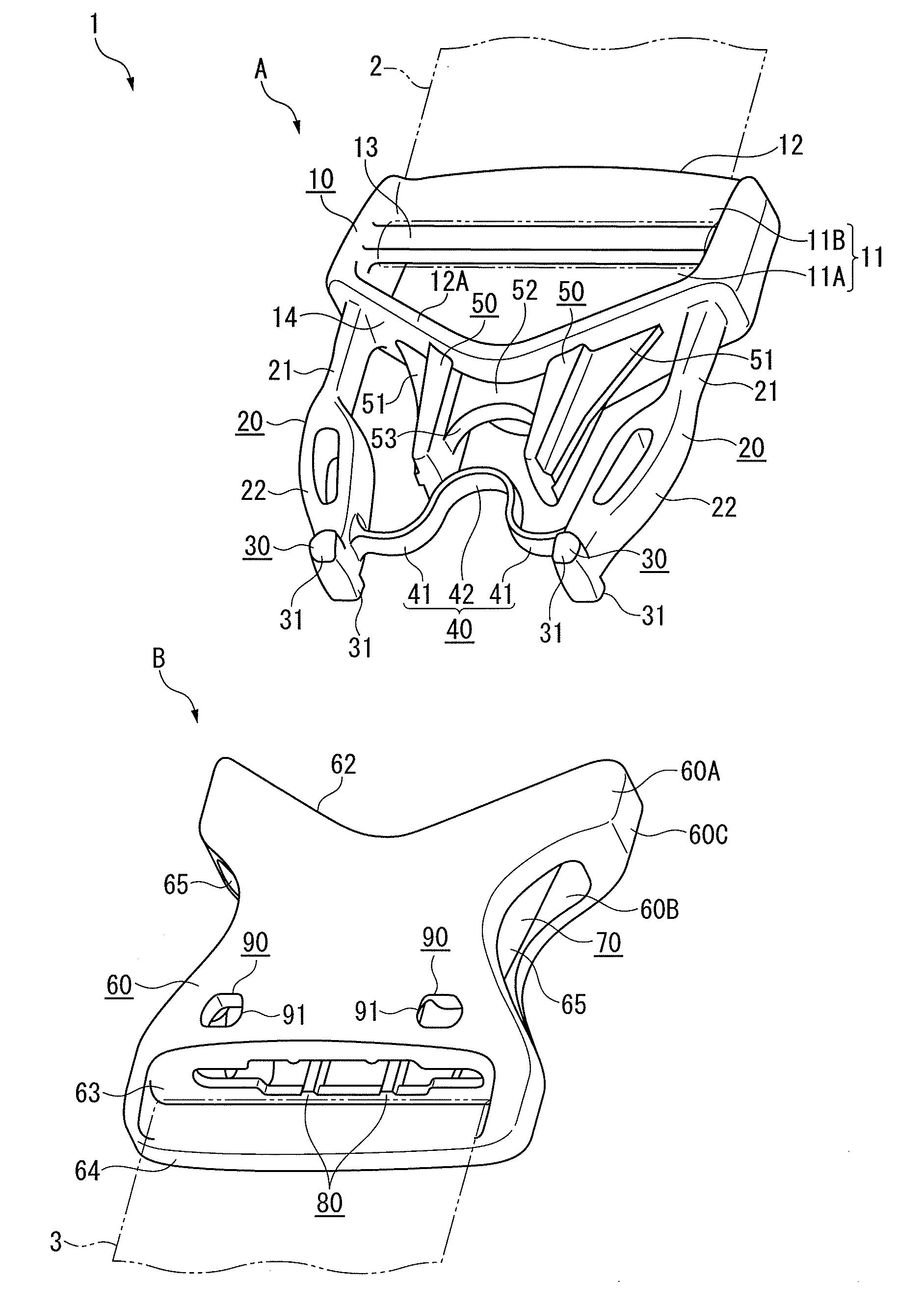
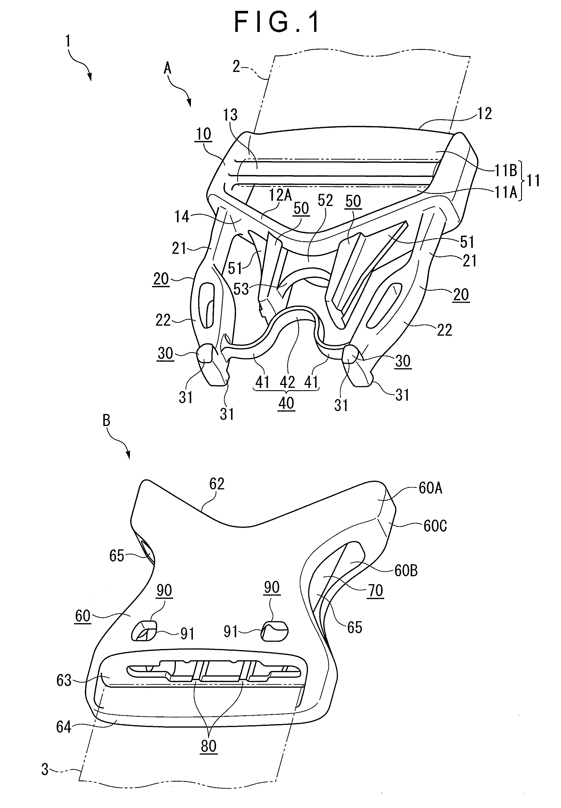
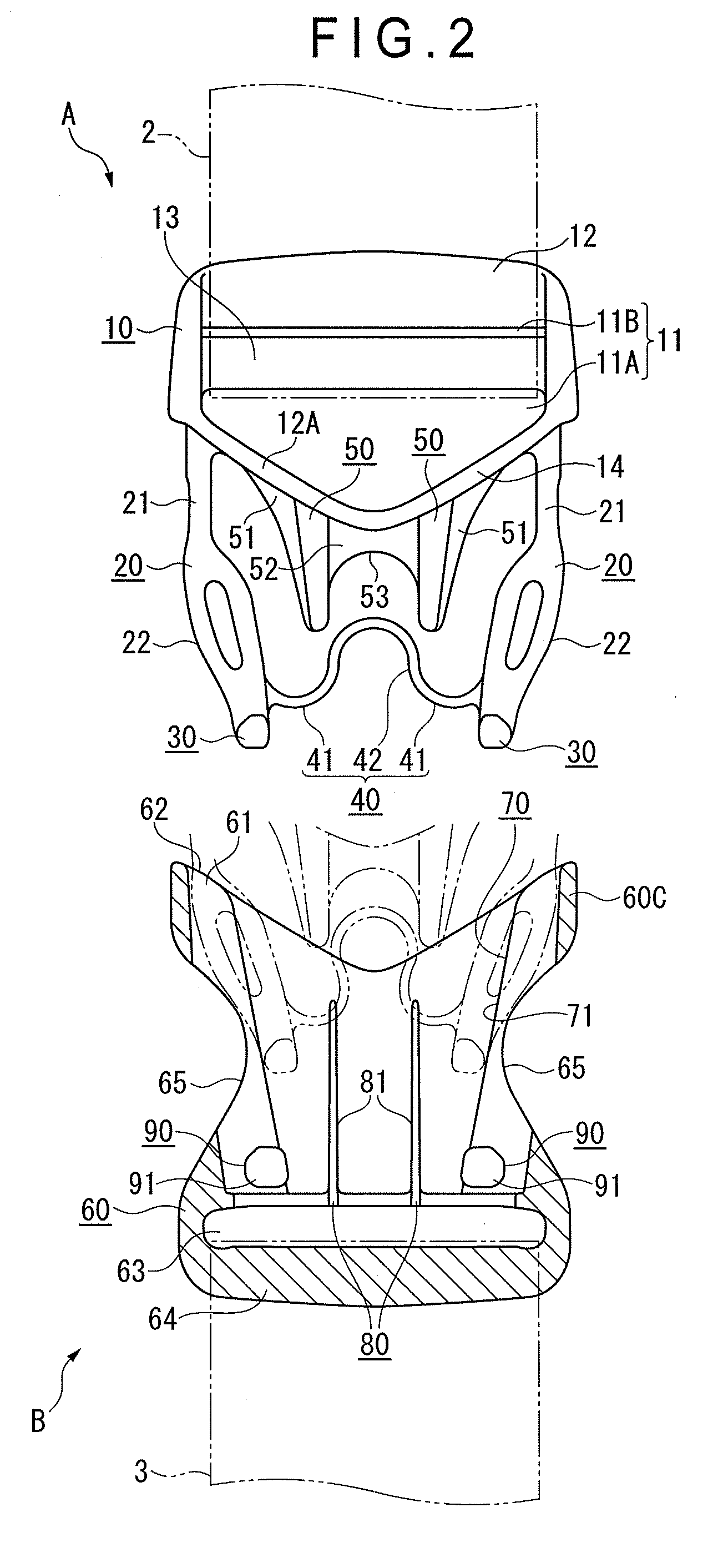
[0045]FIG. 1 is a perspective view showing a buckle in disengagement according to a first exemplary embodiment. FIG. 2 is a partially-cutaway plan view showing the buckle in disengagement. FIG. 3 is a partially-cutaway plan view showing the buckle in engagement.

[0046]As shown in these figures, the buckle 1 according to the first exemplary embodiment for coupling and separating ends 2 and 3 of a string member includes a male member A being integrally formed of a synthetic resin and a female member B also being integrally formed of a synthetic resin and into which the male member A is inserted to be engaged therewith. Materials of the male member A and female member B are not limited to the synthetic resin, but may be other materials such as metal.

[0047]The male member A includes: a base 10; a pair of legs 20 that project in substantially parallel with each other from both widthwise sides of the base 10 (a widthwise direction being perpendicular ...

second exemplary embodiment

[0084]FIG. 7 is a partially-cutaway plan view showing a buckle in disengagement according to a second exemplary embodiment. FIG. 8 is a partially-cutaway plan view showing the buckle in engagement. FIG. 9 shows the buckle when the legs are deformed inward. In the following description of these figures, the same elements as the first exemplary embodiment will be denoted by the same reference symbols, and the description thereof will be omitted or simplified.

[0085]As shown in these figures, a buckle 5 according to the second exemplary embodiment is different in the structure of the linking body and the projecting portions from the buckle 1 according to the first exemplary embodiment.

[0086]A linking body 40A according to the second exemplary embodiment is curved in an inverted U-shape that extends from the inside surfaces of the distal ends of the pair of legs 20 such that the center thereof is closest to the base 10. Specifically, the parallel portions 41 of the linking body 40 accord...


PUM


Abstract

A buckle includes a male member and a female member. The male member includes: a base; a pair of legs that project from the base; engaging portions that are provided on the legs to be engageable with the female member; and a linking body that links the pair of legs. The linking body includes a curved portion that is curved such that the middle thereof is closest to the base. A pair of projecting portions that are substantially parallel with an insertion direction of the male member extend from the base to be disposed outside the curved portion such that the curved portion is interposed therebetween. With this arrangement, the linking body for linking the pair of legs can be disposed with less possibility that other objects are caught in a space in the male member and without increasing a length dimension in the insertion direction more than necessary. The male member can be stably held relative to the female member against a torsion force.

Description

TECHNICAL FIELD[0001]The invention relates to a buckle that includes a male member and a female member. Specifically, the invention relates to a buckle that is used to couple and separate a string member.BACKGROUND ART[0002]There has been used a buckle for coupling and separating both ends of one string member or coupling and separating two string members.[0003]The buckle includes a male member and a tubular female member. The male member is attached to one of members, which are to be coupled with each other. The female member is attached to the other member. The male member includes: a base; a pair of legs that respectively project from both widthwise sides of the base, the pair of legs being elastically deformable in a direction intersecting an insertion direction of the male member; and engaging portions that are respectively provided on the pair of legs, the engaging portions being engageable with the female member.[0004]When the male member is inserted in the female member, the...

Claims


Application Information

Patent Timeline
IPC IPC(8): A44B11/25
CPCA44B11/266A44B11/2592Y10T24/45581Y10T24/4077Y10T24/45984Y10T24/45225Y10T24/4086Y10T24/45529
Inventor KANEKO, HITOSHIUEHARA, RYOICHIRO
Owner YKK CORP
Why Eureka
Try Eureka