Method and apparatus for producing non linear sound attenuation

a non-linear and sound attenuation technology, applied in the direction of electrical equipment, deaf-aid sets, ear treatment, etc., can solve the problems of reducing the acoustical compliance of the ear protector, reducing the flexibility of the diaphragm, and thereby limited flexibility, so as to achieve greater sound attenuation, constant level of attenuation, and high audibility

Inactive Publication Date: 2010-12-30
ETYMOTIC RES
View PDF7 Cites 19 Cited by
  • Summary
  • Abstract
  • Description
  • Claims
  • Application Information

AI Technical Summary

Benefits of technology

[0008]Certain embodiments of the present technology provide a device for attenuating sound within the ear canal where the amount of sound attenuated is greater for higher external sound levels than for lower sound levels. Certain embodiments of the present technology provide an ear protector for insertion into the

Problems solved by technology

The flexibility of the diaphragm is thereby limited to its contact location at the holes in the plate.
The reduction in flexibility correspondingly decreases the acoustical compliance of the ear protec

Method used


Image

  • Method and apparatus for producing non linear sound attenuation
  • Method and apparatus for producing non linear sound attenuation
  • Method and apparatus for producing non linear sound attenuation

Examples


Embodiment Construction

[0032]While the present invention is susceptible of embodiment in many different forms, there is shown in the drawings and will herein be described in detail certain preferred embodiments. It should be understood that the present disclosure is to be considered as an exemplification of the principles of the present technology, and is not intended to limit the broad aspect of the invention to the embodiments illustrated.

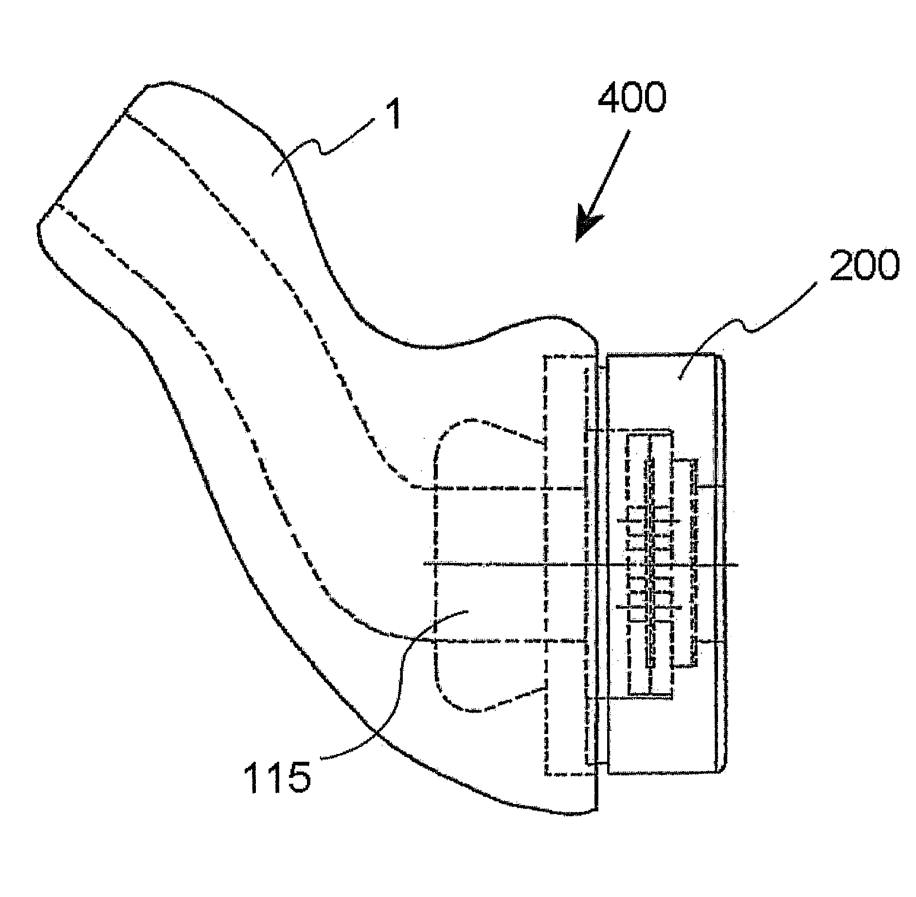
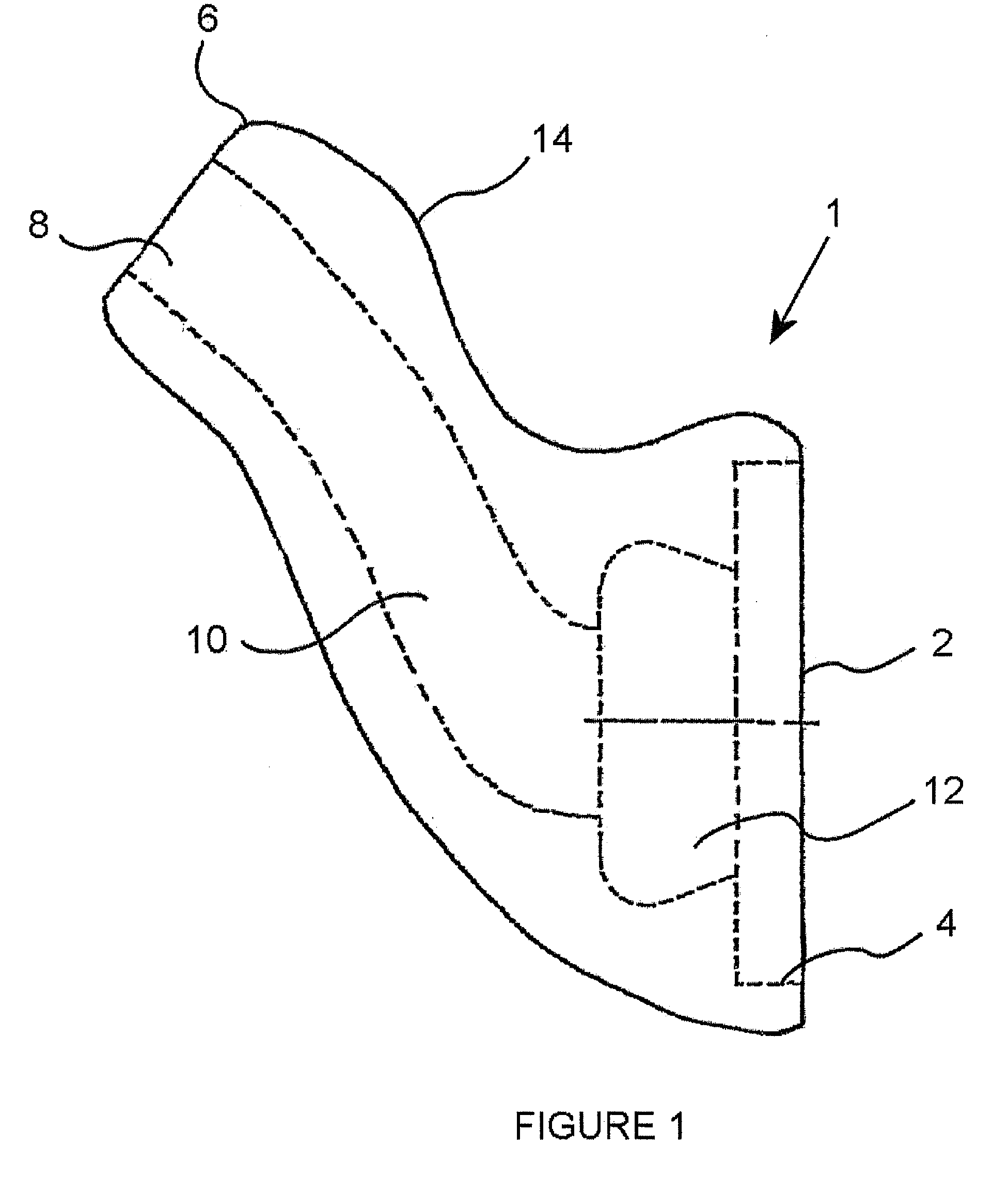
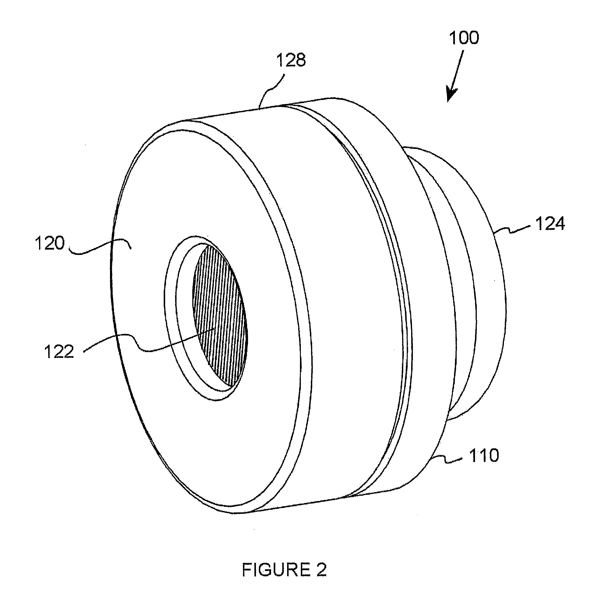
[0033]In the Figures, like elements are identified by numerals. FIG. 1 depicts an earmold 1 for insertion into the ear canal. The present invention is not meant to be limited by the size, shape or structure of the earmold 1. The invention is intended to be used with any earmold that is adapted to receive the ear protector 100 and form an adequate seal when inserted into the ear canal. However, the shape, material and structure of the ear protector 100 itself may be insertable into an ear, making the earmold unnecessary. A variety of different earmolds 1 are provided by...


PUM


Abstract

Certain embodiments of the present technology provide a sound attenuator for reducing high level sounds within the ear canal while maintaining high audibility for lower level sounds. The sound attenuator comprises a housing with a passageway for passing external sound, a damping member to restore resonance within a plugged ear, and a disc interposed across the passageway. The disc comprises a cavity, at least one hole through said disc and a flexible diaphragm positioned across the cavity. At a sound pressure level less than that of a predetermined value the flexible diaphragm expands upon an increase in the external sound pressure level maintaining a near constant level of attenuation. For sound pressure levels at or greater than that of the predetermined value the diaphragm contacts the interior surface of the cavity, thereby limiting the flexibility of the diaphragm and increasing the level of attenuation provided by the attenuator.

Description

FIELD OF THE INVENTION[0001]Certain embodiments of the present invention relate to methods for reducing the noise within an ear canal. More specifically, certain embodiments of the present invention relate to methods and apparatuses for providing non linear noise attenuation such that the attenuation is higher for high level external sounds than for lower level external sounds.BACKGROUND OF THE INVENTION[0002]It is highly documented that military personnel exposed to blasts from firearms, explosions and other high level peak noises are at high risk for hearing loss. Sound pressure levels (SPLs) over 160 dB that occur over periods as short as even a few milliseconds are sufficient to cause damage to the unprotected ear. Exposure to the peak noises caused by gunfire or other explosions adds hearing loss to the long list of risks and dangers encountered by soldiers on the battle field. One means to prevent hearing loss is to wear a noise attenuating device such as ear plugs or earmuffs...

Claims


Application Information

Patent Timeline
IPC IPC(8): A61F11/06
CPCA61F2011/085A61F11/08A61F11/085
Inventor KILLION, MEADSCICLUNA, RON
Owner ETYMOTIC RES
Why Eureka
Try Eureka