Blender assembly and method for producing a preparation using said assembly

a technology of assembly and assembly, which is applied in the direction of flow mixers, mixing methods, mixers, etc., can solve the problems of limited powder introduction flow, cleaning and loss of products, and the terms of cleaning the outside recirculation hos

Active Publication Date: 2011-02-03
VMI INC
View PDF6 Cites 17 Cited by
  • Summary
  • Abstract
  • Description
  • Claims
  • Application Information

AI Technical Summary

Benefits of technology

[0009]The invention aims to resolve these problems by proposing a blender device making it possible to effectively disperse particles in a blend, to introduce said particles with a high flow and to decrease product losses.
[0016]Furthermore, the introduction of the powders can be more significant because it is possible to increase the vacuum level in a vat equipped with such a device without, however, the particles being projected against the upper portion of the vat.
[0017]Moreover, the blender assembly equipped with such a device does not require a hard-to-clean outside recirculation hose.
[0018]Lastly, the blender device according to the invention makes it possible to decrease the implementation time of the device to completely incorporate particles into the preparation.
[0020]Thus, the device is compact and easy to install on a blender assembly.
[0024]In one embodiment, the engine block includes two coaxial rotors. This embodiment makes it possible to further decrease the production time of the preparation.

Problems solved by technology

However, depending on the viscosity of the blend in the vat, an excessively high vacuum level causes too fast a passage of the particles through the blend and the suctioned particles stick against the upper portion of the vat; this creates cleaning and loss-of-product problems.
However, this method poses problems in terms of cleaning the outside recirculation hose.
Furthermore, the introduction flow of the powder is limited by the dimensions of the outside hose and by the circulation flow therein.

Method used


Image

  • Blender assembly and method for producing a preparation using said assembly
  • Blender assembly and method for producing a preparation using said assembly
  • Blender assembly and method for producing a preparation using said assembly

Examples


Embodiment Construction

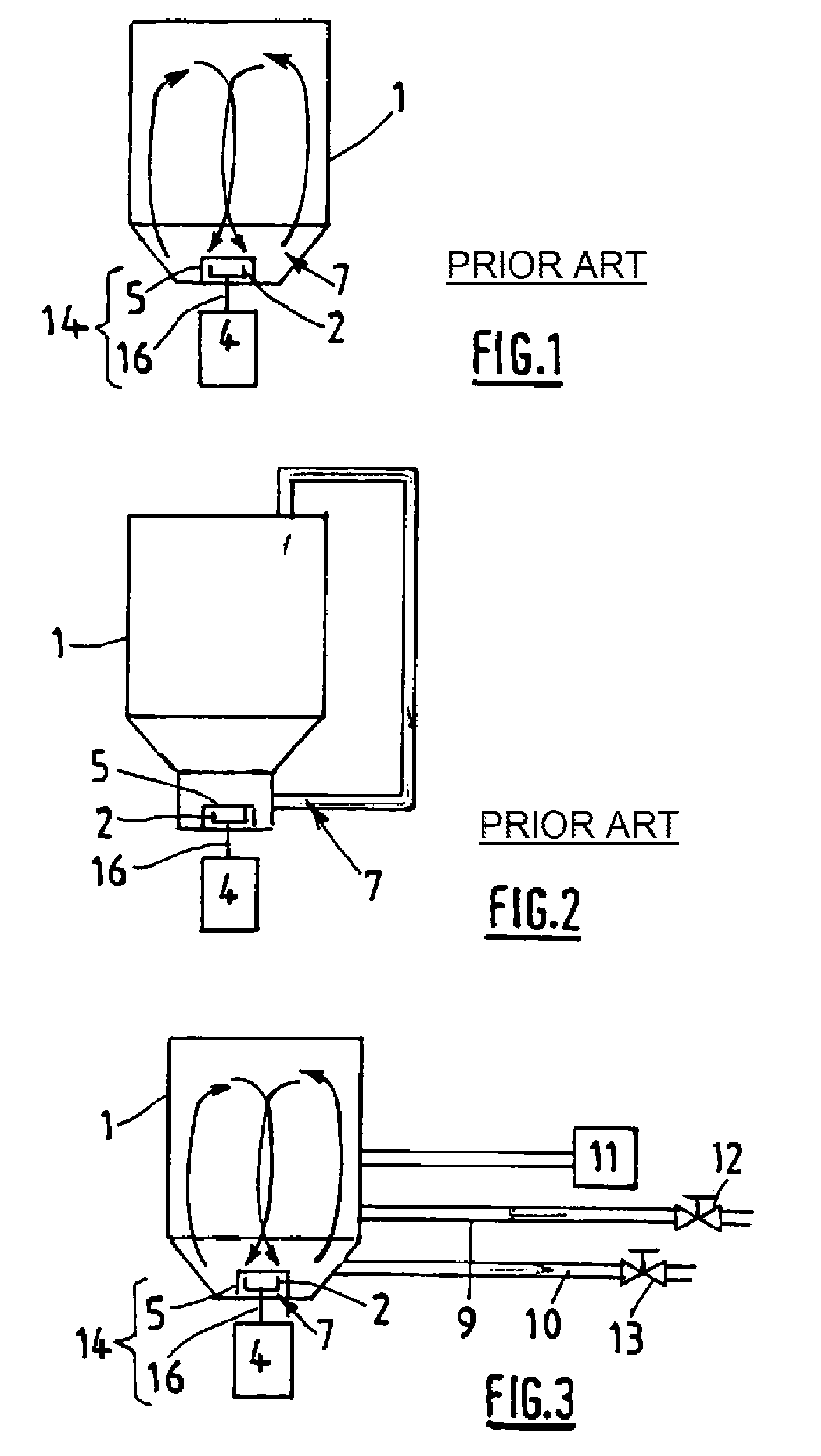
[0044]FIG. 3 diagrammatically illustrates a blender assembly, according to the invention. This assembly comprises a vat 1, a blender device 14, admission means 9 and evacuation means 10 for fluids.

[0045]At least two fluids intended to be blended in the vat 1 are conveyed by the admission means 9, pass through the vat 1 and are evacuated by the evacuation means 10. The admission means 9 and evacuation means 10 each include a line for passage of the fluids and a gate 12, 13 making it possible to regulate the admission and evacuation flow.

[0046]The blender assembly is also equipped with means, such as a pump 11, making it possible to form a vacuum inside the vat 1. In operation, the depression reigning inside the vat can extend between 0 and 0.99 bar.

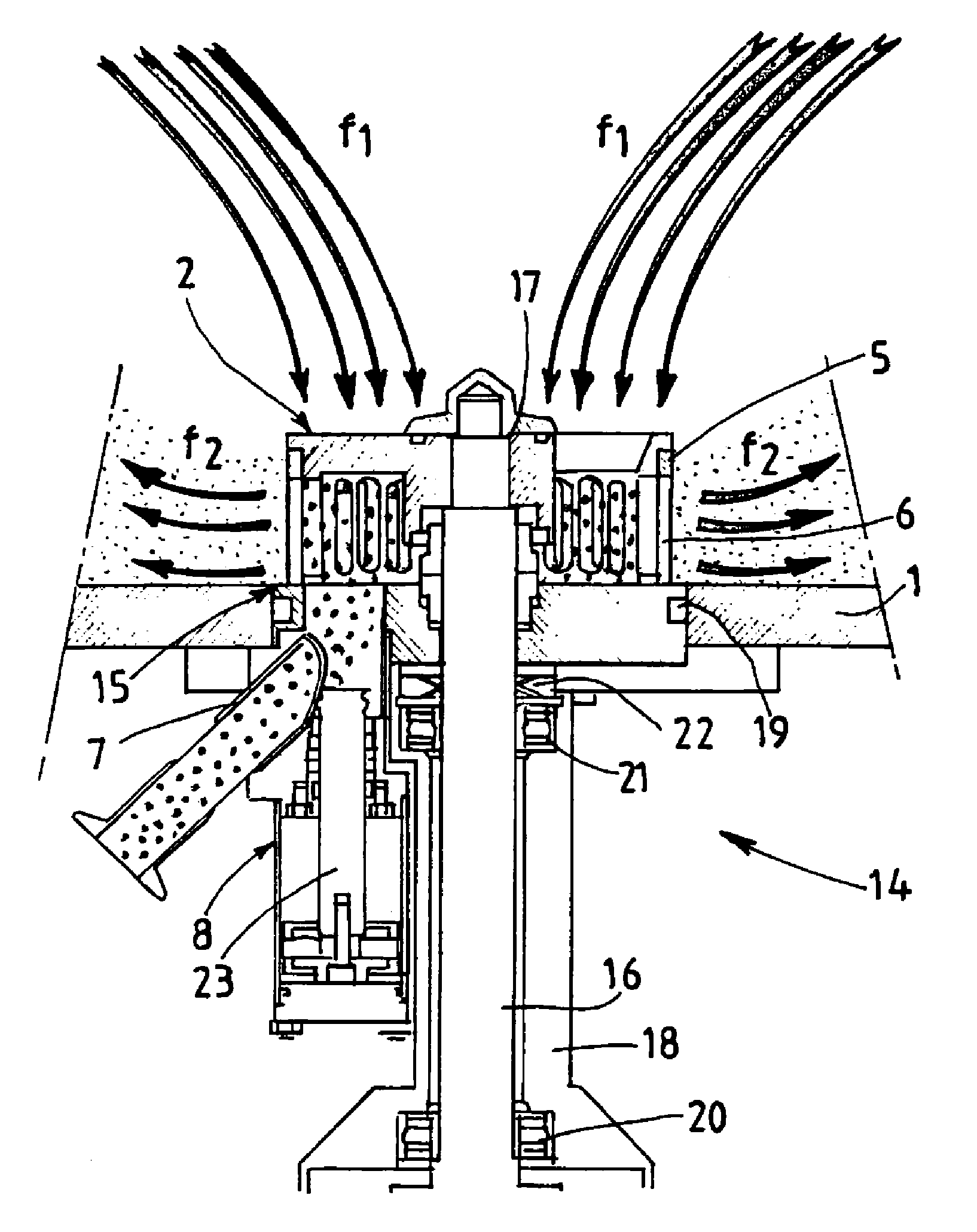
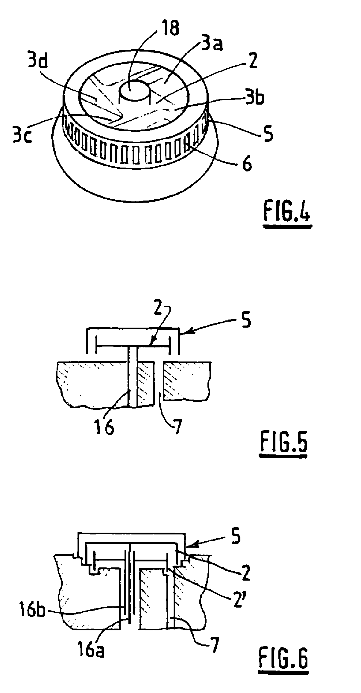
[0047]The blender device according to the invention includes a rotor 2 that rotates inside an annular ring 5.

[0048]The rotor 2 engages with motor means 4 in order to be rotated and includes blending blades 3a, 3b, 3c, 3d arranged to axiall...


PUM

PropertyMeasurementUnit
pressureaaaaaaaaaa
non-miscibleaaaaaaaaaa
suctionaaaaaaaaaa

Abstract

The invention relates to a blender device comprising: a rotor (2) designed to engage with motor means (4) in order to be rotated; and an annular ring (5) enclosing the rotor (2) and having at least one axial orifice and a plurality of radial orifices (6) for the passage of the blend; and an admission duct (7) for admitting particles intended to be incorporated into the blend, leading into the interior of said annular ring (5). The invention also relates to a blender assembly equipped with such a device and a process for producing an emulsion.

Description

TECHNICAL FIELD OF THE INVENTION[0001]The invention concerns a blender device, a blender assembly equipped with such a device and a method for producing a preparation.[0002]The device as well as the blender assembly are particularly intended for producing a preparation, and more particularly dispersing particles in a preparation.BACKGROUND OF THE INVENTION[0003]In the prior art, it is known to produce preparations by blending substances in a vat and introducing powdered particles into the vat in order to incorporate them in the blend.[0004]Such preparations are commonly produced for pharmaceutical, cosmetic or agri-food industry applications . . . . For pharmaceutical or cosmetic applications, the incorporated particles can in particular form the active ingredient of the composition and must then be incorporated into the blend in very precise proportions.[0005]In order to produce these preparations, blender assemblies are known. According to the most widespread technology, these inc...

Claims


Application Information

Patent Timeline
Patent Type & Authority Applications(United States)
IPC IPC(8): B01F13/06B01F3/12B01F25/60B01F27/906
CPCB01F3/0807B01F3/1221B01F7/164B01F2215/0032B01F15/0258B01F2215/0014B01F2215/0031B01F15/0201B01F23/41B01F23/53B01F27/812B01F35/71B01F35/718B01F2101/06B01F2101/21B01F2101/22
Inventor CHEIO DE OLIVEIRA, JOSEDAHERON, HENRIRICARD, PASCAL
Owner VMI INC
Why Eureka
Try Eureka