Cable Knee Brace System

a knee brace and cable technology, applied in the field of cable knee brace system, can solve the problems of high risk of injury to the knee, unfavorable use, impracticality, etc., and achieve the effect of reducing the proneness of the knee, increasing the effectiveness of the brace, and preventing the arm from hyper-extension

Inactive Publication Date: 2011-04-28
FLEMING DARREN
View PDF1 Cites 112 Cited by
  • Summary
  • Abstract
  • Description
  • Claims
  • Application Information

AI Technical Summary

Benefits of technology

[0006]It is the object of the invention to provide a knee bracing system that bolsters the body's natural ligaments to reduce the knees proneness to injury or re-injury.
[0008]The cable knee brace system of this invention can be tailored or adapted to prior art (conventional) braces increasing their effectiveness.
[0009]It is also anticipated by the Applicant that this cable knee brace system can be adapted to the elbow to prevent the arm from hyper extending. A humorous plate would substitute for the femoral plate 4, a radius plate would substitute for the tibial plate 2, and bicep plate would substitute for the femoral back plate 5 creating the differential resistive force across the elbow joint preventing hyperextension of the arm.

Problems solved by technology

The human knee is a complex mechanism that is highly vulnerable to injury in sports like football, hockey, skiing, snowboarding, and motocross.
In these kinds of physically demanding sports the Anterior Cruciate Ligament (ACL) and Medial Collateral Ligaments (MCL) are commonly injured.
Of course this would be impractical and undesirable.
Conventional braces are limited in their effectiveness resisting excessive joint movement that causes injury to the knee.
Even when the strapping devices are tightened to the point of discomfort, they have limited effect preventing excessive movement of the knee joint when the leg is subjected to these forces.

Method used


Image

  • Cable Knee Brace System
  • Cable Knee Brace System
  • Cable Knee Brace System

Examples


Embodiment Construction

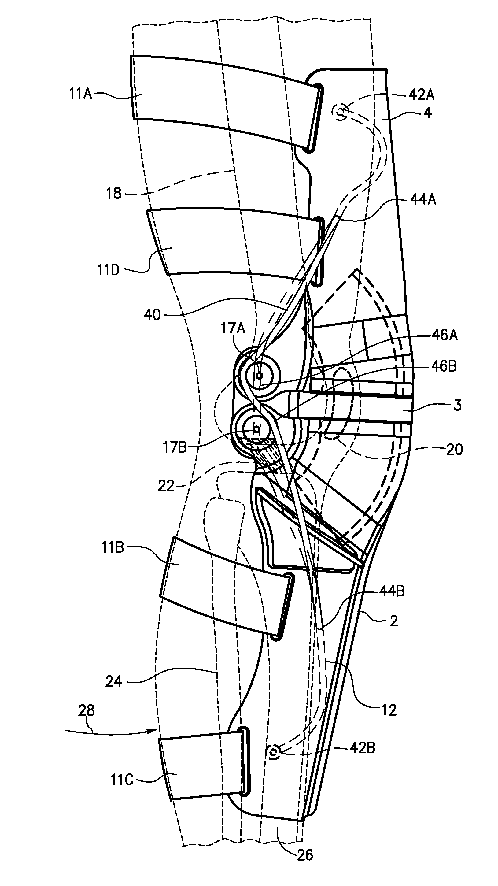
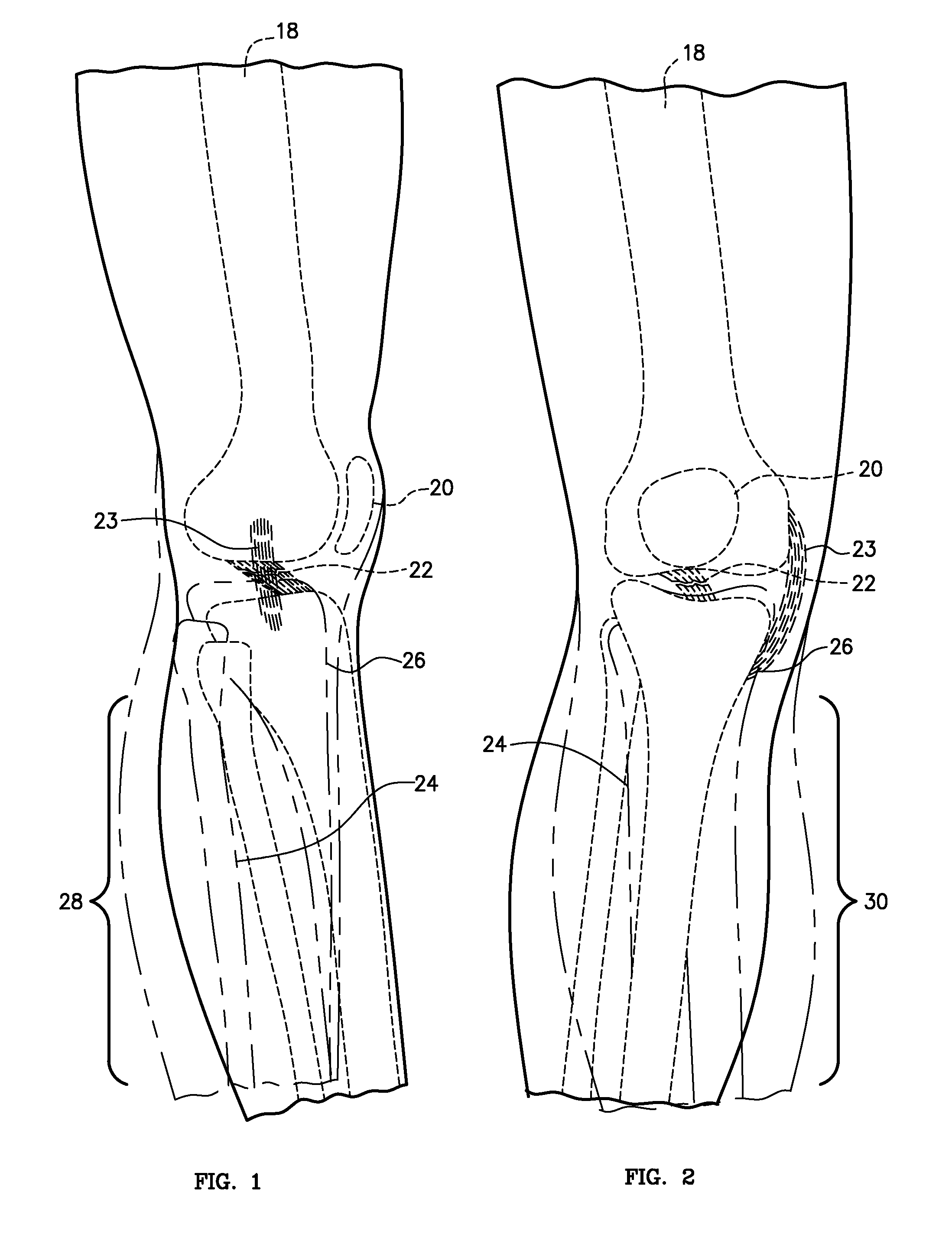
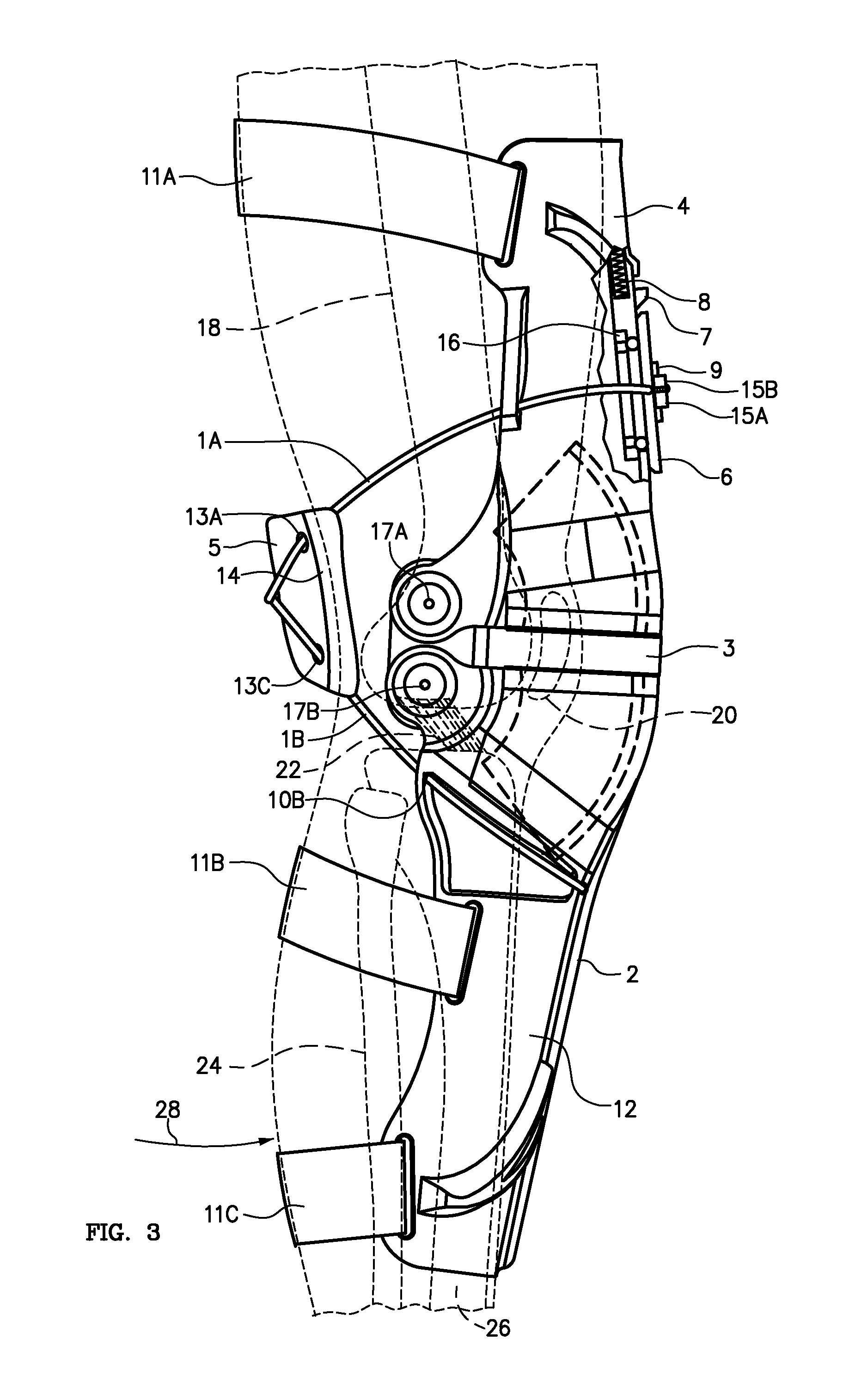
[0023]To be effective preventing injuries to the ACL 22 and or MCL 23 a knee brace must prevent the tibia bone 26 from moving forward (hyper extending), see FIG. 1, or laterally bending and or rotating (twisting), see FIG. 2, with respect to the femur bone 18. The patella 20 and fibula bone 24 are shown for completeness. The knee brace of this invention as best shown in FIGS. 3, 4, 5, 6, 7, 8, 9, and 10, which like references refer to like elements throughout the several views, introduces a novel cable system that more effectively prevents hyper extension, lateral bending and or lateral rotation of the knee joint.

[0024]FIG. 3 shows the primary cable system of this invention creating an effective differential force to the tibia 26 relative to the femur 18 and reinforcing the ACL 22. When the primary cable 1 of this system is properly tensioned the brace acts like the body's own ACL 22 becoming taut as the leg extends resisting the forward movement of the tibia bone 26, with respect t...


PUM


Abstract

It is the object of the invention to provide a knee bracing system that bolsters the body's natural ligaments to reduce the knees proneness to injury or re-injury. The invention is a cable system that acts much like the body's natural ACL and MCL. The cables are routed around the knee joint in a way that resists the forces that cause excessive joint movement and injury to the ACL and or MCL. As the leg travels through the range of motion the cables provide external hyper extension, bending, and rotation support preventing the tibia bone from moving forward (hyper extending) or twisting (lateral rotation) and or laterally bending with respect to the femur.

Description

RELATED APPLICATIONS[0001]This present application is a continuation-in-part of U.S. patent application Ser. No. 11 / 744,213 filed on May 3, 2007, entitled Cable Brace System.FIELD OF THE INVENTION[0002]Invention relates to orthopedic devices for knees, and more specifically to a knee brace system utilizing a cable to mechanically support the knees natural ligaments.BACKGROUND OF THE INVENTION[0003]The human knee is a complex mechanism that is highly vulnerable to injury in sports like football, hockey, skiing, snowboarding, and motocross. In these kinds of physically demanding sports the Anterior Cruciate Ligament (ACL) and Medial Collateral Ligaments (MCL) are commonly injured. The ACL controls forward movement of the tibia relative to the femur (hyper extension) and lateral rotation of the tibia with respect to the femur (over rotation). The MCL controls lateral movement of the tibia with respect to the femur. Hyper extending the leg and or laterally rotating or twisting or latera...

Claims


Application Information

Patent Timeline
Patent Type & Authority Applications(United States)
IPC IPC(8): A61F5/00
CPCA61F5/0123A61F2005/0179A61F2005/0167A61F2005/0137
Inventor FLEMING, DARREN
Owner FLEMING DARREN
Why Eureka
Try Eureka