Image transmission apparatus and control method therefor, and image display system

a technology of image transmission and control method, which is applied in the direction of electric digital data processing, instruments, computing, etc., can solve the problems of pcs taking a considerable load of resolution conversion processing, unnecessary load on the network, and deterioration of images, so as to reduce the load of image transfer processing and prevent deterioration of images

Inactive Publication Date: 2012-01-26
CANON KK
View PDF10 Cites 20 Cited by
  • Summary
  • Abstract
  • Description
  • Claims
  • Application Information

AI Technical Summary

Benefits of technology

[0010]The present invention has been made in view of the problems, and reduces the load of image transfer processing and prevents deterioration of an image by image reduction processing in a system including an information processing apparatus that transmits the image and a display apparatus that displays the transmitted image.

Problems solved by technology

However, there are problems, such as the connection is troublesome, the connection from a remote place is difficult, and there is a limitation in the number of PCs that can be connected at the same time.
If the number of display pixels of the PC is greater than that of the display apparatus, there is a problem that the image data is transmitted to the display apparatus without change, and an unnecessary load is imposed on the network.
However, in the configuration described in Japanese Patent Laid-Open No. 2006-106158, when the resolutions between the PC and the display apparatus differ, there is a problem that it is necessary to perform the resolution conversion processing within the PC and the PC should take a considerable load of the resolution conversion processing.
Furthermore, there is a problem that the image is deteriorated by reduction processing of the image because the image needs to be reduced when the number of display pixels of the PC is greater than the number of display pixels of the display apparatus.

Method used


Image

  • Image transmission apparatus and control method therefor, and image display system
  • Image transmission apparatus and control method therefor, and image display system
  • Image transmission apparatus and control method therefor, and image display system

Examples


first embodiment

[0034]Exemplary embodiments of the present invention will be described in detail in accordance with the accompanying drawings. The dimensions, shapes and relative positions of the constituent parts shown in the embodiments should be changed as convenient depending on various conditions and on the structure of the apparatus adapted to the invention, and the invention is not limited to the embodiments described herein.

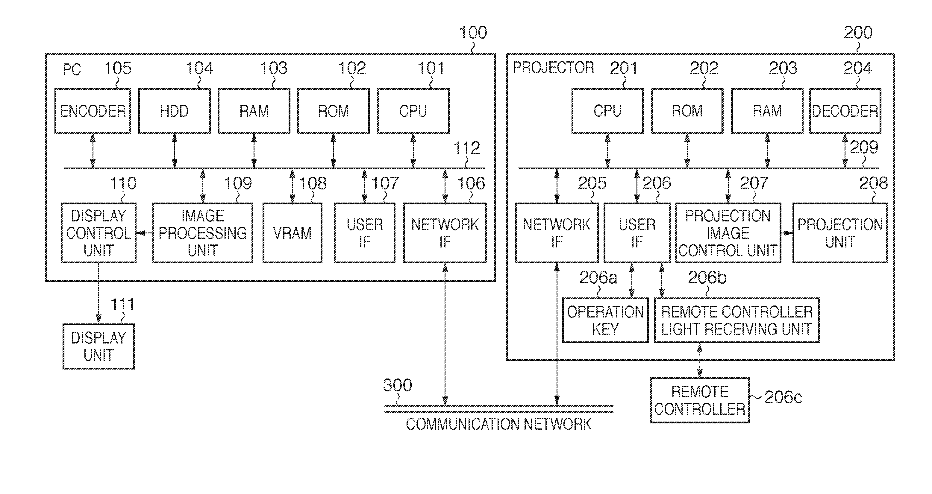
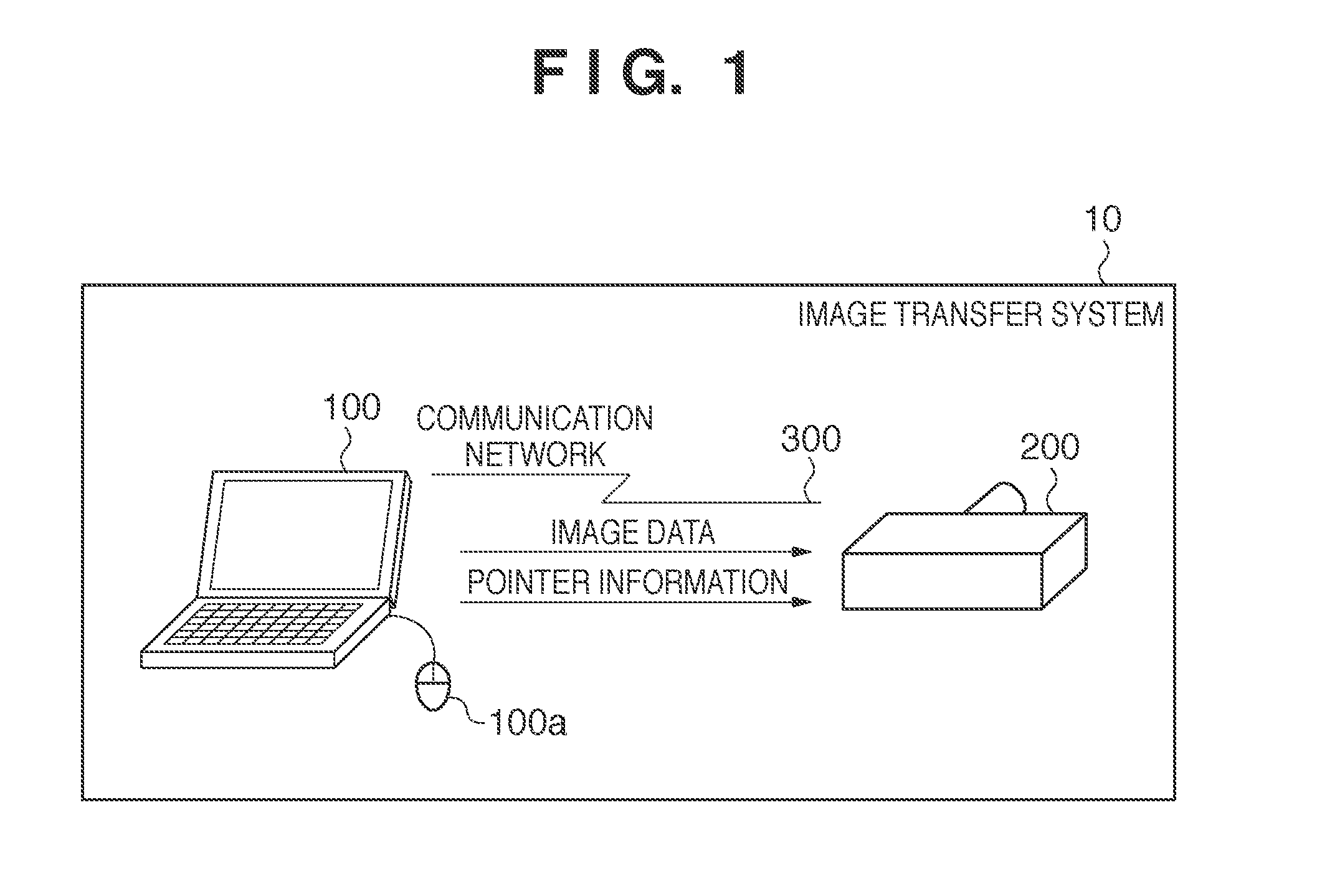
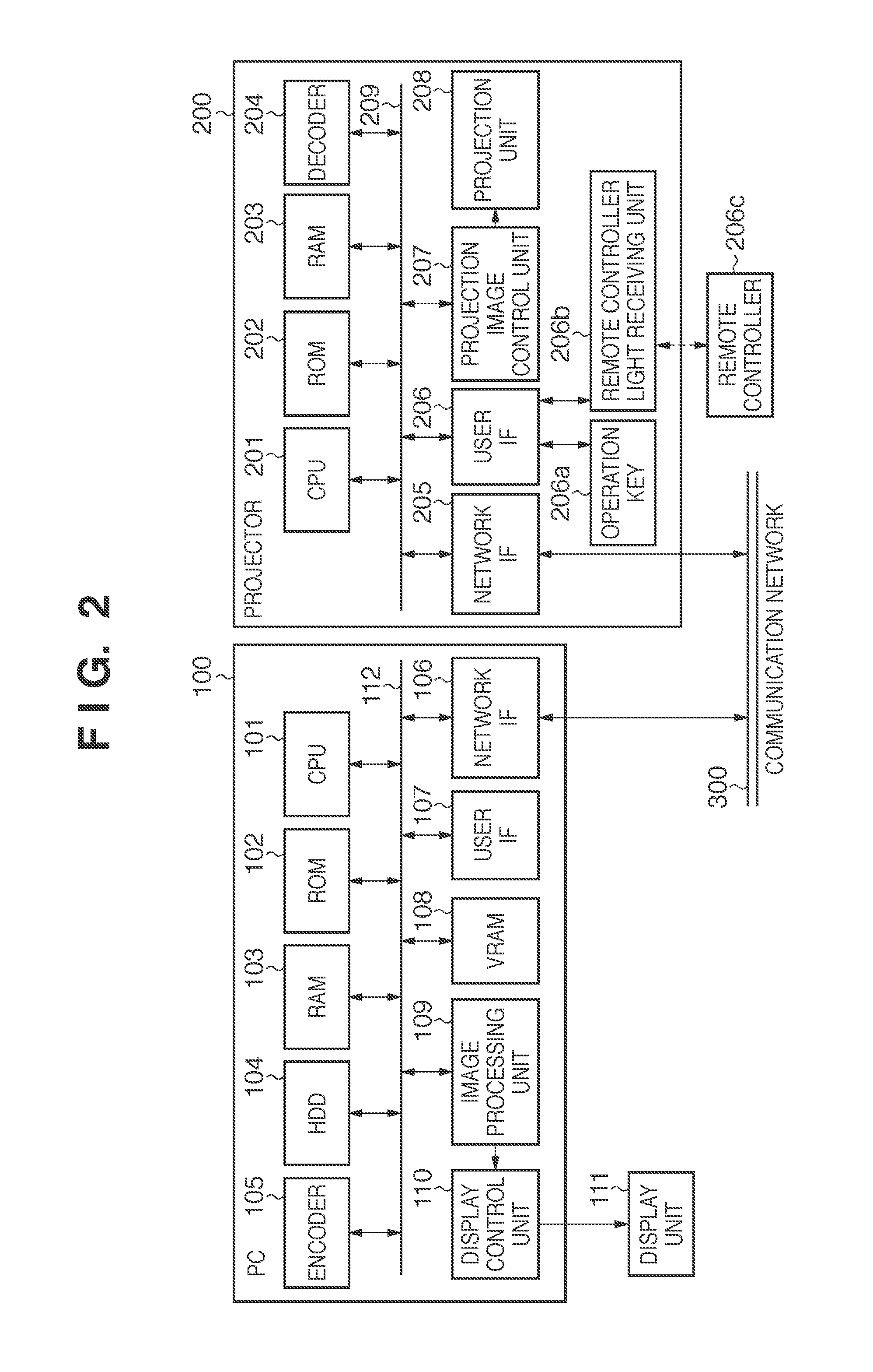
[0035]FIG. 1 is a diagram showing the configuration of an image transfer system 10 using an image processing apparatus according to embodiments of the present invention. An image transfer system 10 includes a PC 100 (image processing apparatus) and a projector 200 (display apparatus), and the PC 100 and the projector 200 form a communication network 300 through a LAN. The PC 100 includes a window system. The window system herein denotes a mechanism for allocating specific areas to a plurality of tasks to multiplex the screen output. An example of the window system includ...

second embodiment

[0056]An operation according to a second embodiment of the image communication system will be described with reference to FIGS. 8 to 10. An area to be captured is arbitrarily designated on the screen in the first embodiment. The second embodiment describes a case in which the area to be captured is a specific window.

[0057]Based on a command from the CPU 101, the PC 100 reads an image transfer program from the HDD 104 to start the window designation processing shown in FIG. 8. A flow of the window designation processing will be described with reference to FIG. 8. The CPU 101 controls the components of the PC 100 to execute the operation of the flow chart of FIG. 8 based on an application expanded in the RAM 103 of the PC 100.

[0058]When the window designation processing is started, the CPU 101 acquires the number of display pixels of the display area of the projector 200 through the network IF 106 (step S31). In response to the inquiry of the number of display pixels from the PC 100, ...

third embodiment

[0072]An operation according to a third embodiment of the image communication system will be described with reference to FIGS. 11 and 12. The area to be captured is designated in the PC 100 (external image processing apparatus) in the first and second embodiments. The third embodiment describes a case in which the area to be captured is designated from the projector 200.

[0073]Based on a command from the CPU 201, the projector 200 reads a capture area designation program from the ROM 202 to start the screen transfer instruction processing shown in FIG. 11. A flow of the area designation processing will be described with reference to FIG. 11. It is assumed in the description that the screen transfer program as described in the first and second embodiments is launched in the PC 100 before the start of the area designation processing of FIG. 11 by the projector 200.

[0074]The projector 200 acquires information of a window (window information) currently displayed by the PC 100 from the PC...


PUM


Abstract

An image of an area smaller than the number of horizontal pixels and the number of vertical pixels of an external image display apparatus is extracted from a display area if the number of horizontal pixels of a part of a display area designated by a designation unit is greater than the number of horizontal pixels of the external image display apparatus acquired by an acquisition unit and / or if the number of vertical pixels of the part of the display area designated by the designation unit is greater than the number of vertical pixels of the external image display apparatus acquired by the acquisition unit.

Description

BACKGROUND OF THE INVENTION[0001]1. Field of the Invention[0002]The present invention relates to an image transmission apparatus and control method therefore, and an image display system.[0003]2. Description of the Related Art[0004]In recent years, there have been more opportunities to use a projector that projects onto a screen an image based on an image signal received from a PC during a presentation at a conference, a workshop, and the like.[0005]In general, the PC and the projector transmit and receive the image signal through an image cable. However, there are problems, such as the connection is troublesome, the connection from a remote place is difficult, and there is a limitation in the number of PCs that can be connected at the same time. Therefore, an image transfer system that connects the PC and the projector through a network has been drawing attention in recent years.[0006]Conventionally, an image processing apparatus such as a PC captures a specific window or an image ...

Claims


Application Information

Patent Timeline
Patent Type & Authority Applications(United States)
IPC IPC(8): G09G5/00G06F3/048G06F3/0484
CPCG09G5/14G09G2350/00G09G2340/0407G06F3/1454
Inventor INAGAKI, KENSUKE
Owner CANON KK
Why Eureka
Try Eureka