Lens for projection and projection-type display apparatus

a technology of projection and display apparatus, applied in the field of projection and projection type display apparatus, can solve the problems of large inability to meet such a demand, and difficulty in suppressing the generation of chromatic aberrations, so as to achieve the effect of reducing the generation of aberrations, increasing the size of the apparatus, and large siz

Active Publication Date: 2012-03-08
FUJIFILM CORP
View PDF1 Cites 13 Cited by
  • Summary
  • Abstract
  • Description
  • Claims
  • Application Information

AI Technical Summary

Benefits of technology

[0012]In view of the foregoing circumstances, it is an object of the present invention to provide a lens for projection that can set a space between the lens for projection and a light valve to structure an optical system for guiding light output from a light source to the light valve and an optical system for guiding light modu...

Problems solved by technology

However, projectors in which lenses for projection having relatively large F-numbers, as disclosed in Patent Documents 1 through 3, are mounted do not meet such a demand.
Meanwhile, a projector in which a lens for projection having a small F-number (fast lens), as disclosed in Patent Documents 4 and 5, is mounted may meet the demand, but the reduction in the F-number (faster lens) causes a problem that the size of the appa...

Method used


Image

  • Lens for projection and projection-type display apparatus
  • Lens for projection and projection-type display apparatus
  • Lens for projection and projection-type display apparatus

Examples


specific examples

[0133]With reference to FIGS. 4 through 8 and FIGS. 9A-9D through 13A-13D, and Tables 1 through 6, Examples 1 through 5 of the lens for projection of the present invention and numerical data or the like of the examples will be described together.

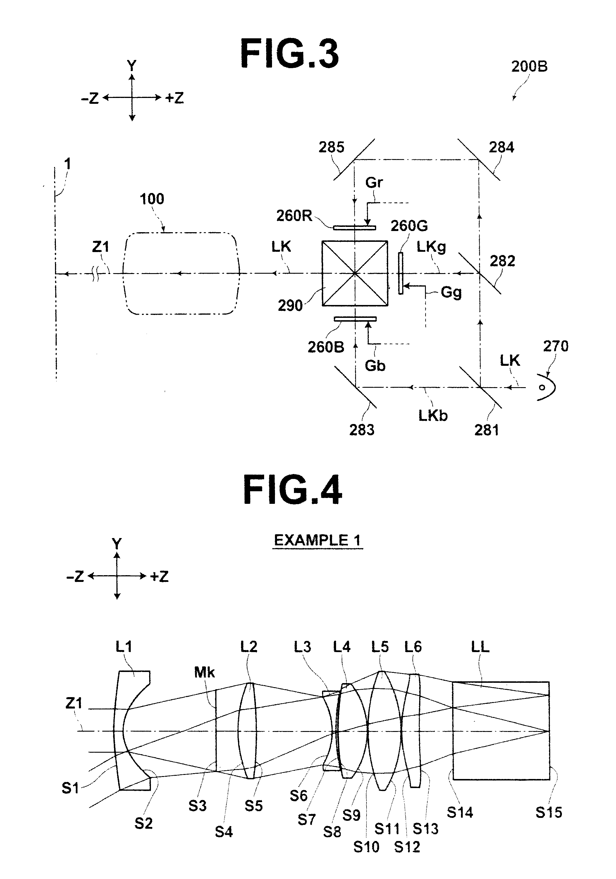
[0134]FIGS. 4 through 8 are schematic cross sections illustrating the structure of the lenses for projection in Examples 1 through 5, respectively.

[0135]In FIG. 4, which is a cross section illustrating a lens for projection in Example 1, optical paths of light passing through the lens for projection are also illustrated. FIG. 4 shows that the reduction side of the lens for projection in Example 1 is telecentric. Further, in the lenses for projection in the other examples, namely, Examples 2 through 5, the reduction side of the lens for projection may be also telecentric.

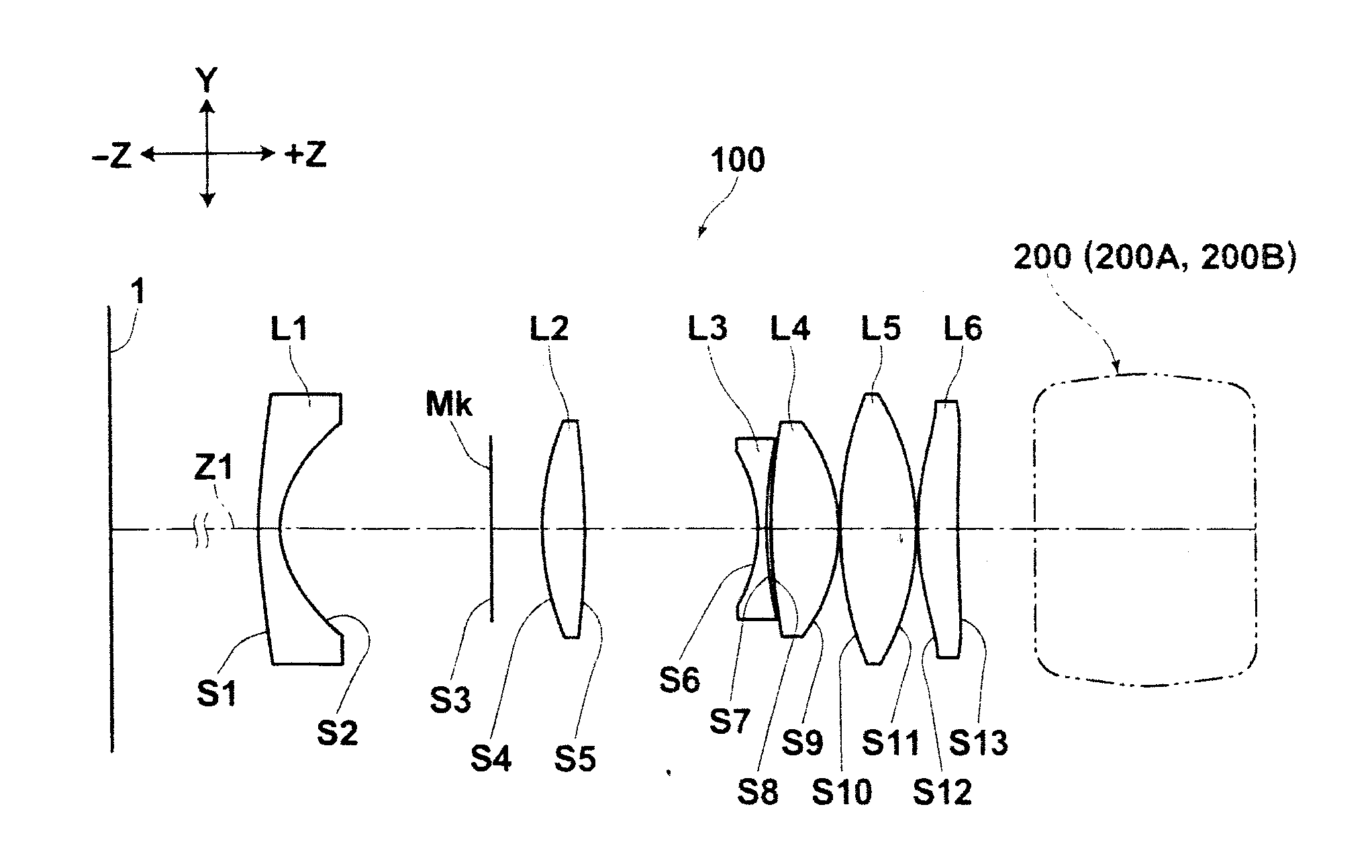
[0136]In FIGS. 4 through 8, signs L1, represent lenses constituting the lenses for projection. The signs L1, L2, . . . correspond to the order of arrangement of lenses from t...


PUM


Abstract

A negative first lens having a concave surface facing the reduction side of a lens for projection, a positive second lens having a convex surface facing the magnification side of the lens for projection, a negative third lens having a concave surface facing the magnification side, a positive fourth lens having a convex surface facing the reduction side, a positive fifth lens, and a positive sixth lens are arranged in this order from the magnification side, and the reduction side of the optical system is telecentric. Further, the following formula (A) is satisfied:
1.2≦Bf/f≦2.5  (A), where
Bf: back focus in air of the entire lens system of the lens for projection, and
f: focal length of the entire lens system.

Description

BACKGROUND OF THE INVENTION[0001]1. Field of the Invention[0002]The present invention relates to a lens for projection and a projection-type display apparatus, and particularly to a lens for projection substantially consisting of six lenses and a projection-type display apparatus using the lens for projection.[0003]2. Description of the Related Art[0004]In recent years, projection-type display apparatuses (also called as projectors) rapidly spread. The projection-type display apparatuses project images represented by image data output from personal computers or the like onto screens. As such projectors, a projector that projects, onto a screen, light that has been output from a light source and modulated by a light valve is known. As the light valve, a transmission-type liquid crystal device, a reflection-type liquid crystal device, a DMD (Digital Micromirror Device), and the like are known. In the DMD, micromirrors, the angles of which are changeable, are arranged.[0005]Such a proj...

Claims


Application Information

Patent Timeline
IPC IPC(8): G02B13/04G02B13/18
CPCG02B13/18G02B13/04
Inventor YAMAMOTO, CHIKARA
Owner FUJIFILM CORP
Why Eureka
Try Eureka