Control apparatus for vehicle and control method therefor

Active Publication Date: 2012-05-03
JATCO LTD +1
View PDF13 Cites 35 Cited by
  • Summary
  • Abstract
  • Description
  • Claims
  • Application Information

AI Technical Summary

Benefits of technology

[0006]It is, therefore, an object of the present invention to provide a control apparatus for a vehicle and a control method therefor which are capable of improving the drive-ability while the engagement element between the driving source and the driving wheels is suppressed from being heat generated and being deteriorated.

Problems solved by technology

However, when a vehicle driver depresses a brake pedal so that the vehicle is in the vehicle stopped state during the WSC traveling mode, the slip state of the clutch is continued so that there is a possibility of a heat generation of the clutch and a deterioration thereof.
However, if a hydraulic pressure supplied to the clutch is excessively reduced, there is a possibility that a state in which the clutch is released toward a more released side from a state in which a transmission torque capacity of the clutch becomes substantially zero (corresponding to a generation start point of the transmission torque capacity) occurs.
When, in this state, the vehicle driver releases the brake pedal and depresses an accelerator pedal to start the vehicle, a considerable time is taken for the clutch to start to have the transmission torque capacity so that a delay in the vehicle start, a start shock, and so forth occur.
Consequently, there is a possibility of reduction in drive-ability of the vehicle.

Method used


Image

  • Control apparatus for vehicle and control method therefor
  • Control apparatus for vehicle and control method therefor
  • Control apparatus for vehicle and control method therefor

Examples


Embodiment Construction

[0023]Reference will hereinafter be made to the drawings in order to facilitate a better understanding of the present invention.

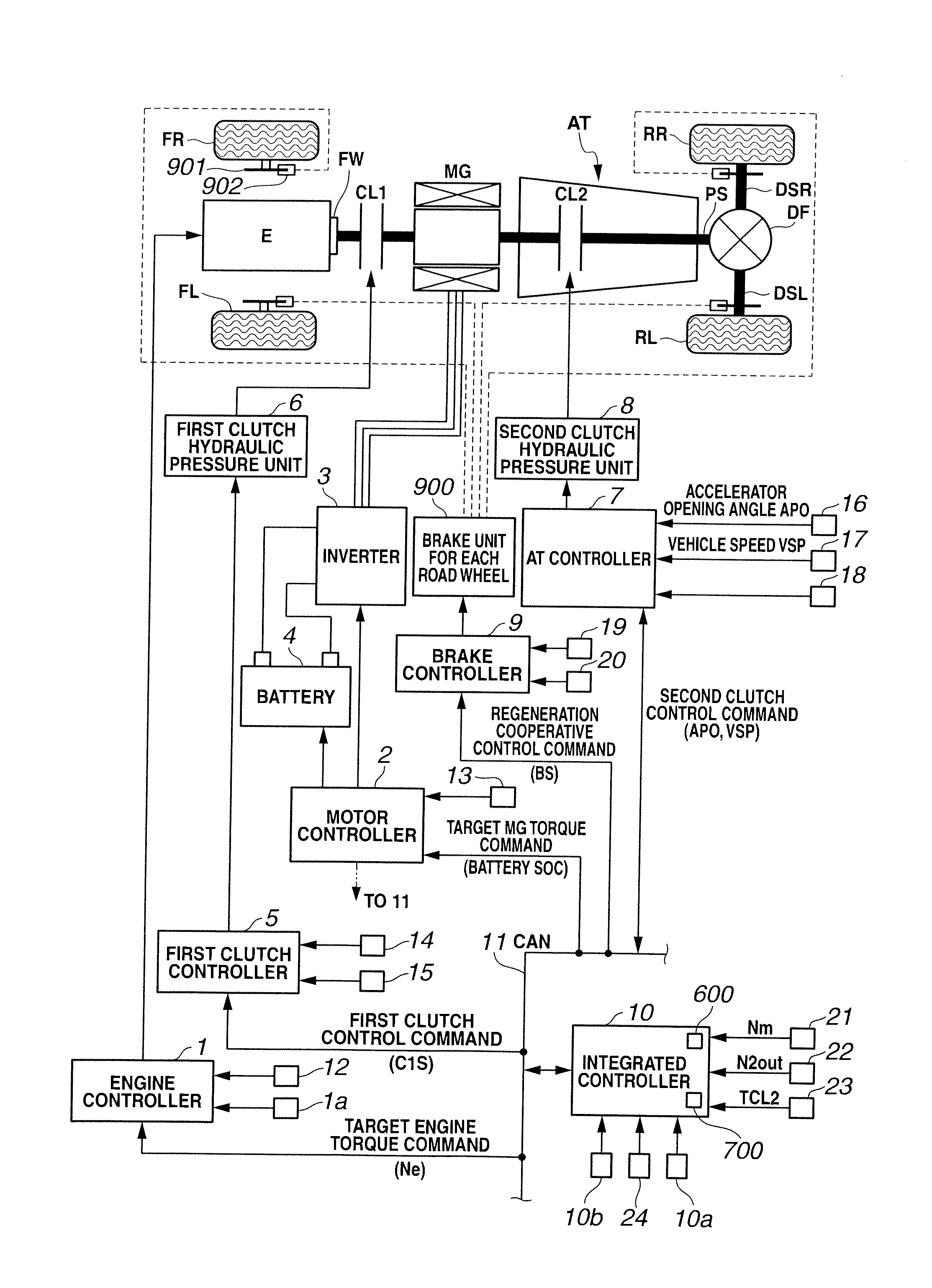
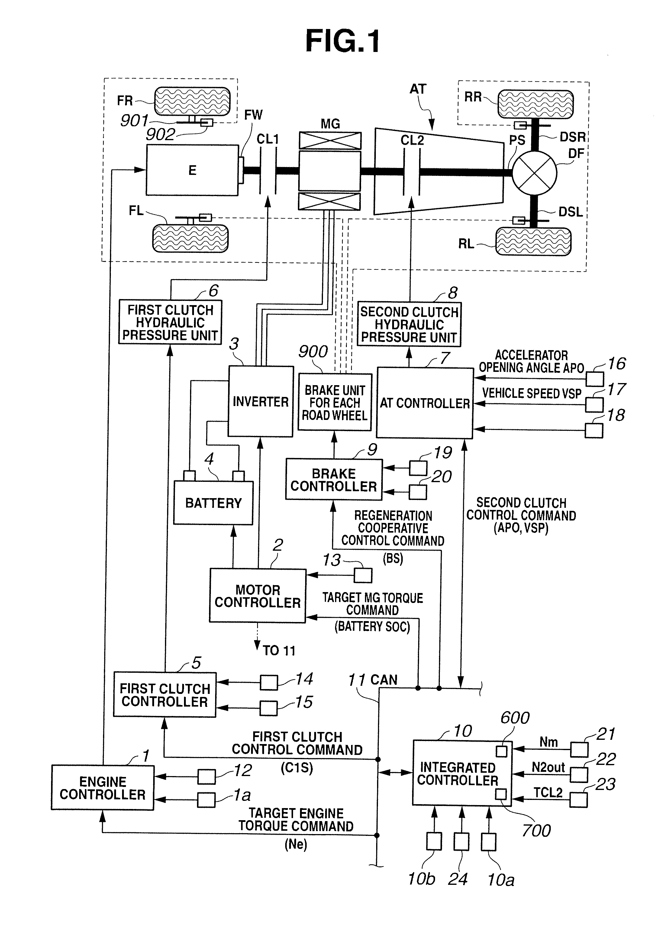
[0024]First, a structure of a drive train of a hybrid vehicle will be described below. FIG. 1 shows a whole system configuration view representing a rear wheel drive (so called, front engine rear wheel drive (FR)) hybrid vehicle to which a control apparatus in a preferred embodiment according to the present invention is applicable.

[0025]The drive train of the hybrid vehicle, as shown in FIG. 1, includes: an engine E; a first clutch CL1; a motor / generator MG; an automatic transmission AT; a propeller shaft PS; a differential DF; a left drive shaft DSL; a right drive shaft DSR; a left rear road wheel RL (driving wheel); and a right rear road wheel RR (driving wheel). It should be noted that FL in FIG. 1 denotes a left front road wheel and FR in FIG. 1 denotes a right front road wheel.

[0026]Engine E is, for example, a gasoline engine and a valve opening angle ...


PUM


Abstract

In control apparatus and method for a vehicle, the vehicle including a traveling mode (a WSC traveling mode) in which a slip control is performed for a clutch (second clutch CL2) and a revolution speed control is performed for the driving source such that a revolution speed at a driving source side of the clutch becomes higher than that at a driving wheel side of the clutch by a predetermined revolution speed, an actual torque of a driving source of the vehicle is detected, a command hydraulic pressure is reduced from an initial command hydraulic pressure and a post-correction command hydraulic pressure is set on a basis of the command hydraulic pressure when a variation in the actual torque of the driving source along with the reduction of the command hydraulic pressure is determined to end, when a vehicle stopped state is determined to occur during the traveling mode.

Description

BACKGROUND OF THE INVENTION[0001](1) Field of the Invention[0002]The present invention relates to a control apparatus for a vehicle and a control method therefor in which a slip control for an engagement element disposed between a power source (driving source) and driving wheels is performed.[0003](2) Description of related art[0004]A Japanese Patent Application First Publication No. 2010-077981 published on Apr. 8, 2010 exemplifies a previously proposed control apparatus for a vehicle. This Patent Application Publication describes a technique carrying out an engine use slip mode (hereinafter, referred to as a WSC (Wet Start Clutch) traveling mode) in which driving forces of both of an engine and a motor are used to start the vehicle while slipping a clutch intervened between the motor and driving wheels.SUMMARY OF THE INVENTION[0005]However, when a vehicle driver depresses a brake pedal so that the vehicle is in the vehicle stopped state during the WSC traveling mode, the slip stat...

Claims


Application Information

Patent Timeline
IPC IPC(8): G06F7/00B60L50/16B60W30/18
CPCB60W10/02B60W10/06B60W10/08B60W20/00B60W30/18027B60W30/186B60W2510/0638B60W2510/083B60W2520/04B60W2520/10B60W2540/10B60W2710/025B60W2710/081Y02T10/62B60W2510/0225B60W2710/085B60W2710/083B60W2710/027B60W2510/0657B60W30/18B60W20/40B60W20/11B60W2510/084
Inventor AKEBONO, HIROMICHIYAMAMOTO, HIDEHARUMIURA, KOTASAITO, HISASHI
Owner JATCO LTD
Why Eureka
Try Eureka